Advertisement
Quick Links
Wiring Instructions
Tamper Switch
Series C200, C300, LFC300
Sizes 2½"–10"
Series 2000SS, 3000SS
Sizes 2½"–12"
WARNING
!
Read this Manual BEFORE using this equipment.
Failure to read and follow all safety and use information
can result in death, serious personal injury, property
damage, or damage to the equipment.
Keep this Manual for future reference.
Wiring the Tamper Switch
Tamper switches integrated on the OSY-TS model of Series
C200, C300, LFC300, 2000SS, and 3000SS assemblies add
protection against fire.
The supervisory tamper switch consists of two SPDT switches.
The device is designed to send a signal when the valve is closed
and when the switch is removed from the valve. In the neutral
position, the switch indicates the valve is fully open. Closing
the valve causes the switch rod to come out of the valve stem
groove, activating the switch. Removing the device also acti-
vates the switch.
Connect the wires to a fire alarm control panel in accordance
with the schematic diagram and the wiring notes on page 2.
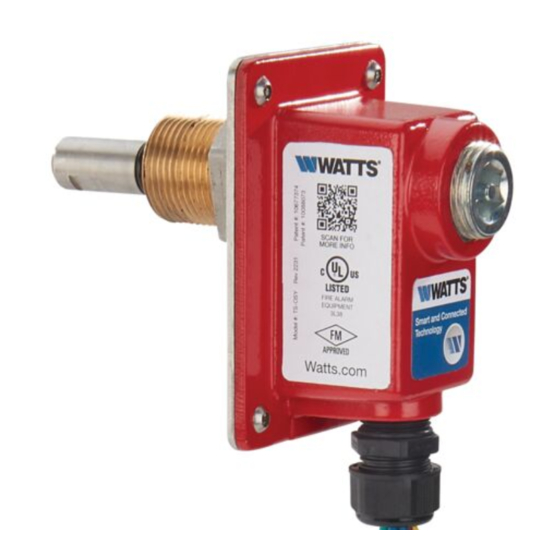
Switch rod in valve stem groove
OSY gate valve with integrated tamper switch
CAUTION
!
Before wiring supervisory switches in fire protection systems,
refer to the following standards:
NFPA 13: Standard for the Installation of Sprinkler Systems
NFPA 25: Inspection, Testing, Maintenance of Water-based Fire
Protection Systems
NFPA 70: National Electrical Code
NFPA 72: National Fire Alarm Code
CSA C22.1 NO.1 Canadian Electrical Code, Part 1, Safety
Standard for Electrical Installations Section 32
CAN/ULC-S524, Standard for Installation of Fire Alarm Systems
WARNING
!
• Metallic conduit required by NEC for proper grounding conduit
joint must be sealed with a conductive sealant.
• Install switch in accordance with National Electrical Code and/
or local ordinances.
• Wiring methods shall be in accordance with CSA C22.1,
Canadian Electrical Code, Part 1, Safety Standard for Electrical
Installations, Section 32 and CAN/ULC-S524, Standard for
Installation of Fire Alarm Systems Assure All Devices Are
Properly Grounded.
IS-A-FireTamperSwitch
Advertisement

Related Manuals for Watts AMES C200 Series


Summary of Contents for Watts AMES C200 Series
- Page 1 IS-A-FireTamperSwitch Wiring Instructions Tamper Switch Series C200, C300, LFC300 Sizes 2½"–10" Series 2000SS, 3000SS Sizes 2½"–12" WARNING Read this Manual BEFORE using this equipment. Failure to read and follow all safety and use information can result in death, serious personal injury, property damage, or damage to the equipment.
- Page 2 USA: Backflow T: (978) 689-6066 • F: (978) 975-8350 • AmesFireWater.com USA: Control Valves T: (713) 943-0688 • F: (713) 944-9445 • AmesFireWater.com Canada: T: (888) 208-8927 • F: (905) 481-2316 • AmesFireWater.ca Latin America: T: (52) 55-4122-0138 • AmesFireWater.com IS-A-FireTamperSwitch 2218 © 2022 Watts...