Table of Contents
Advertisement
Quick Links
OPERATION MANUAL
AIR PARTICLE MONITER
To Use in Safety; ····················································· 1
1. Summary ···························································· 2
2. Measurement Principle ·········································· 2
3. Specifications ······················································ 2
4. Profile and Parts ·················································· 3
5. Mounting ···························································· 4
6. Connection ························································· 5
7. Wi-Fi communication ············································· 5
8. Wi-Fi access start-up ············································ 6
9. Web browser screen ··········································· 10
10. Troubleshooting················································ 17
# Certainly perform the right operation by operators perusing this Manual.
1-8-18 Norimatsu-Higashi,Yahatanishi-ku,Kitakyushu 807-0837 Japan
Phone No. (8193)691-3731 Fax No. (8193)691-3735
http://www.matsushima-m-tech.com
FOR
TYPE: PFM-AP01
Contents
TPFMAP-001E
Rev. 3: Oct. 21, 2021
Advertisement
Table of Contents

Related Manuals for Matsushima PFM-AP01

Summary of Contents for Matsushima PFM-AP01
-
Page 1: Table Of Contents
TPFMAP-001E Rev. 3: Oct. 21, 2021 OPERATION MANUAL AIR PARTICLE MONITER TYPE: PFM-AP01 Contents To Use in Safety; ····················································· 1 1. Summary ···························································· 2 2. Measurement Principle ·········································· 2 3. Specifications ······················································ 2 4. Profile and Parts ·················································· 3 5. Mounting ···························································· 4 6. -
Page 2: To Use In Safety
To Use in Safety; - Surely read this Manual in advance before use the product. - Keep this Manual in a certain place to look anytime. - Contents in this Manual may change without previous notice. - About part replacement; Product modification to improve quality will be done very often. -
Page 3: Summary
A signal value of mass concentration ((µg/m3) can be output with calculation by counting PM in the environment. 3. Specifications Type PFM-AP01 Power DC24V±10% Current consumption Less 150mA (in case of DC24V) Minimum particle diameter to be detected 0.3µm (PM0.3) -
Page 4: Profile And Parts
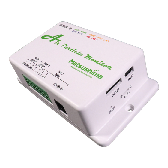
(#3) AC adapter specifications: Output power DC 24.0V/over 0.5A/Center plus 4. Profile and Parts 35.5 Mounting holes M3x2 Fig. 1: Profile of Product and Name of Parts Status of LED Led to be shown condition of devices Green light Normal work (Below threshold) Orange light Work at contact point (Exceeding threshold) Blue light... -
Page 5: Mounting
5. Mounting Please avoid mounting and using under the following circumstances not to be caused any short-life and errors of devices. - Any place to be caused shaking, shocking and breakdown. - Any place of surround temperature out of rang 0℃ to +50℃, surround humidity exceeding 80%RH and under dew condensation. -
Page 6: Connection
6. Connection Power supply will be 2 methods of φ5.5 plug jack (option) and leg spring terminal block. Numbering on the terminal block will be as follows; Current output Power supply Contact point DC4 to 20mA (DC24V±10%) Terminal No. (COM) (NO) (NC) # The power supply must be connected to only one of DC jack or terminal block. -
Page 7: Wi-Fi Access Start-Up
Fig. 6-1: Wi-Fi Access (In case of PC) [In case of AndroidOS/iOS] a. Please access to the network “PFM-AP01-#”from your individual terminal (Tablet/Mobile phone). (# Displaying last triple digits of the MAC address on the product tag for individual identification) Input the password “matsushima”... - Page 8 Select “matsushima” Input Select Fig. 6-2: Wi-Fi Access (In case of AndroidOS/iOS) b. The status LED will be blue light Wi-Fi access to the device can be completed. # Changing the status LED may take over 20 seconds. Wi-Fi access...
- Page 9 c. Please input “10.10.10.1”on the address bar of web browser. Web applications will be displayed on the web browser. # Terminals to be confirmed and browser will be as follows; - Windows PC (Windows10): Microsoft Edge 44.18262.449.0 Google Chrome 86.0.4240.111 - iPhone (iOS 14.1): Safari 604.1 - Android Smart Phone (Android10): Google Chrome 86.0.4240.99 # It may not work properly except for terminals to be confirmed and browser.
- Page 10 e. When displaying the Network setting, please input necessary items on Access point mode or Station mode, and click on the “Apply” button to update. (Example) Input whichever necessary Update after input Fig. 10: Input items on Network Setting # If no necessary to modify the IP address of Access point mode, use the initial value. # Keep the password by individual.
-
Page 11: Web Browser Screen
9. Web browser screen # Previously perform Wi-Fi access start-up according to Item 8. # Please access to “Google Chrome” or “Microsoft Edge” on Windows 10, “Google Chrome” on AndroidOS and “Safari” on iOS. # Please input all alphanumeric characters by one-byte. 9-1. - Page 12 9-2. Screen of Measurement result This is screen to be displayed the measuring results. The measuring point of current output and contact point output will be marked (✔). Also, by color changing on the measuring point, confirming condition of contact point output will be available.
- Page 13 9-3. Screen of Measurement setting This is the screen of parameters setting for measurement. Press the “Apply” button to update after inputting and modifying each value. Fig. 12: Screen of measuring setting (A) Range setting Specify max. range value according to current value 20mA of the selected parameter.
- Page 14 - Moving average Output Ave. value of past output values among the specified times on the [times] parameter for each PM counting. If it is “1”, moving average is not performed. Initial value 1 [times] Range of setting 1 to 60 [times] - Cleanness conversion Select target to calculate conversion value of cleaning level on the list box.
- Page 15 - “Stop” button Stop logging. (B) Log setting Specify when logging. - Sampling period [min] Specify a cycle of data sampling. Initial value: 1 Range of setting 1 to 60min - Target to be logged Select the target data on the check box. # If modifying log setting, please be sure to update before start logging.
- Page 16 Fig. 15: Screen of network setting (A) Access point mode One by one communication mode between Product and PC mounted Wi-Fi - SSID Initial value: PFM-AP01-# #: Display last triple digits of MAC address For individual identification Max. 32 alphanumeric characters by one-byte (Min.
- Page 17 9-6. Screen of Output setting This is the screen to perform mock output testing of current output and contact point output. And, this is the screen to specify actions of contact point output and current output under trouble on Product. “Now testing”...
-
Page 18: Troubleshooting
10. Troubleshooting When the following phenomena occurred, please confirm items corresponding to the phenomena before judgement of breakdown. Item Failure Confirmation/Treatment - Try to perform absolute power supply after confirmed No power wiring. LED has red color flashing. - Set power OFF -> ON. Unable to access to web browser - Please confirm the Wi-Fi access start-up in Item 8.
Need help?
Do you have a question about the PFM-AP01 and is the answer not in the manual?
Questions and answers