Table of Contents
Advertisement
Available languages
Available languages
Quick Links
Electric actuators type EA25-250:
Monitoring
Instruction Manual
The technical data are not binding and not expressly
warranted characteristics of the goods. They are
subject to change. Our General Conditions of Sale apply.
Using the monitoring, the instruction manual of the electric
actuator type EA 25-250 must be observed.
Intended use
Accessory board Monitoring
The monitoring can be used with the electric actuators type EA25, EA45, EA120
and EA250, both with the 24V AC/DC as well as the 100-230V AC version. The
board is to be plugged into the housing of the actuator in the provided slots.
Description
Code
Monitoring
199 190 602
1 Function
The monitoring enables four functions: Cycle time extension, Cycle time
monitoring, Cycle counter and Motor current monitoring.
Nr.
Description
1
Cycle time extension
2
Cycle time monitoring
Cycle counter
3
Monitoring a selected maximum number of cycles
Motor current monitoring
4
Monitoring a selected maximum motor current
2 Assembly of the monitoring board
CAUTION!
Disconnect the actuator from the supply voltage.
1.
Remove housing cover of the electric actuator (loosen the 4 screws,
open cover).
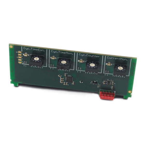
Via the BCD switches 1 to 4 the
monitor settings are made. The
different functions work
independently of one another.
700278094
GFDO_6430 / DE EN/ 04 (06.2022)
© Georg Fischer Piping Systems Ltd
CH-8201 Schaffhausen/Switzerland
Georg Fischer Piping Systems Ltd CH-8201 Schaffhausen
Phone +41 (0)52 631 30 26 / info.ps@georgfischer.com / www.gfps.com
2.
Take the monitoring board out of the packaging and check for
damages.
CAUTION!
Do not touch the board itself. Electrostatic discharge can damage the
components.
3.
Insert board vertical on the backside of the main board onto the red
plug.
CAUTION!
Ensure that the board sits in the lateral guides and snaps.
4.
Make desired settings according to 3 "Settings".
5.
Stick scheme label into housing cover.
6.
Put the cover back in place and fasten it with the 4 screws.
3 Settings
3.1
Cycle time extension
The cycle time extension extends the cycle time of the electric actuator. To do
this, the actuator is moved continuously into the end positions (OPEN or
CLOSE). For the corresponding value please refer to the table below. These
values are valid for 90° actuation. The cycle time is given in seconds.
BCD
EA25
0 (factory setting)
7
1
10
2
13
3
15
4
18
5
20
6
23
7
25
8
28
9
30
3.2
Cycle time monitoring
The cycle time monitoring monitors the duration of a preset cycle time of the
electric actuator. As soon as the cycle exceeds the pre-set time, an error is
reported. For the corresponding value please refer to the table below. These
values are valid for 90° actuation. The cycle time is given in seconds.
EA45
EA120
EA250
7
25
27
10
28
35
13
32
40
15
38
45
18
42
50
20
48
55
23
52
60
25
58
65
28
62
70
30
67
75
Advertisement
Table of Contents

Related Manuals for +GF+ EA25-250


Summary of Contents for +GF+ EA25-250
- Page 1 Electric actuators type EA25-250: 700278094 GFDO_6430 / DE EN/ 04 (06.2022) Monitoring © Georg Fischer Piping Systems Ltd CH-8201 Schaffhausen/Switzerland Georg Fischer Piping Systems Ltd CH-8201 Schaffhausen Instruction Manual Phone +41 (0)52 631 30 26 / info.ps@georgfischer.com / www.gfps.com The technical data are not binding and not expressly warranted characteristics of the goods.
- Page 2 4 Error message EA25 EA45 EA120 EA250 An error can trigger the following: The 7-segment display on the main board illuminates; see illustration below. If the monitoring PCB is installed, the respective LED lights up red on the BCD switch, if its set value is exceeded. ...
- Page 3 Änderungen sind vorbehalten. Es gelten unsere Allgemeinen Verkaufsbedingungen. Unter Verwendung der Überwachung muss die Installationsanleitung des Gehäusedeckel des elektrischen Antriebs entfernen (dazu die vier elektrischen Antriebs Typ EA25-250 beachtet werden. Schrauben lösen und Deckel öffnen). Überwachungsplatine aus der Verpackung entnehmen und auf Bestimmungsgemässe Verwendung Beschädigungen kontrollieren.
- Page 4 Stoppt gelaufen 200 000 Für weitere Fehlercodes der Basisplatine, siehe Bedienungsanleitung des elektrischen Zurücksetzen des Stellzyklenzählers Antriebs Typ EA25-250. Der Stellzyklenzähler wird anhand folgender Schritte zurückgesetzt: Den BCD-Schalter auf Stellung „0“ stellen (diese Position entspricht einer Störmeldung beheben Stellbewegung) Fehlerursache kontrollieren, ggf.
Need help?
Do you have a question about the EA25-250 and is the answer not in the manual?
Questions and answers