
Related Manuals for Accutron FlowTrax IS


Summary of Contents for Accutron FlowTrax IS
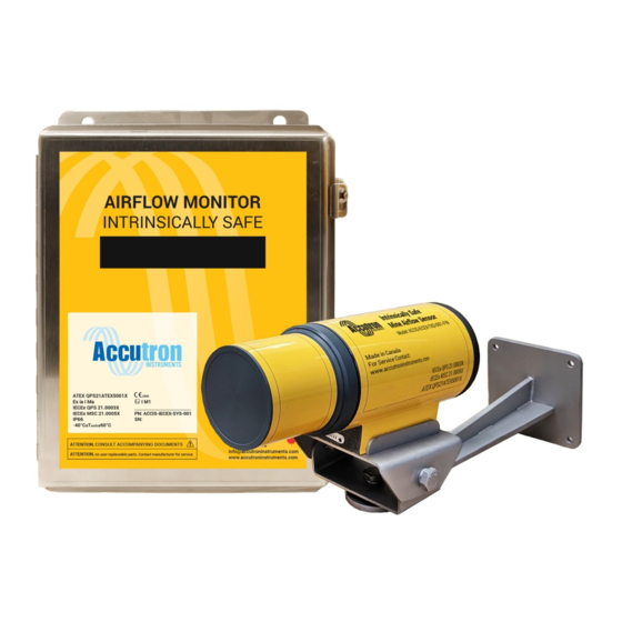
- Page 1 FlowTrax IS Technical Operations Manual V2022.06.21 Visit www.accutroninstruments.com Email info@accutroninstruments.com ACCIS-SYS-002-DR (Drift) Phone 1.705.682.0814 ACCIS-SYS-002-FN (Fan)
- Page 3 Important Notice The ACCUTRON IS line of products is the exclusive copyright property of Accutron Instruments INC. We reserve the right to make changes to the Accutron products and manuals without further notice to improve reliability, function or design. Accutron Instruments INC does not assume any liability arising out of the application or use of any product described herein, nor does it convey any license under its patent rights, nor the rights of others.
-
Page 4: Table Of Contents
Table of Contents Important Notice ............................i Section 1: General Information ........................1 1.1 The Manual ............................1 1.1 Safety Guidelines ..........................2 1.2 Information about your system ......................2 1.3 Accutron IS Series Specifications ......................3 Section 2: Installation............................ 4 2.1 System Explanation .......................... -
Page 5: Section 1: General Information
Section 1: General Information 1.1 The Manual Refer to this manual for proper installation, operation, setup and maintenance of the Accutron IS Instrument. Special attention must be followed to warnings and notices highlighted from the rest of the text to ensure it will stand out. -
Page 6: Safety Guidelines
1.1 Safety Guidelines Warning notices must be observed to ensure personal safety as well as that of others, and to protect the product and the connected equipment. This device should only be set up and operated in conjunction with this manual. Qualified personnel are only authorized to install and operate this equipment in accordance with established safety practices and standards. -
Page 7: Accutron Is Series Specifications
1.3 Accutron IS Series Specifications Connections: Screw terminal Block Type Transducers: 3 ½” (Dia.) X 9 1/8” (L) Display Readout: 16 Characters LCD display. Each digit is 0.57” (H) X 0.24” (W) Power Supply: 12.6VDC intrinsically safe power supply Power Consumption: <... -
Page 8: Section 2: Installation
Section 2: Installation 2.1 System Explanation The Accutron airflow sensors are compact and reliable instruments, especially designed for measuring airflows in mining environments. The Accutron IS Drift System is for airflow measurements in mine drifts whereas the Accutron IS Fan System is for measuring the flow output of large mining fans. Each system consists of an Indicating Transmitter, cabling and two “ultrasonic sensor”... -
Page 9: Choosing A Location
2.2 Choosing a Location The best location to install the instrument is in a straight section of tunnel that is at least 3 tunnel widths long. In such a section, the airflow distribution will be well behaved with a maximum airflow in the center and minimum airflow on the sides (Figure A). -
Page 10: Mounting The Sensors
2.4 Mounting the Sensors When planning a mounting location for the wall mount sensors, we recommend mounting one sensor near the top of the drift or duct and the other sensor located near the bottom downstream from the first on the opposite side, with an “imaginary line” between them intersecting the airflow at a typical angle of 120 degrees. -
Page 11: Section 3: Programming
Section 3: Programming 3.1 Navigation Buttons NAV BUTTONS Select / Enter Down Left PROG Right Navigation Buttons Program Program Switch Reset Button (Bottom left of display board) RESET • To program the settings the programming switch must be in the PROG position. o As of V.4.03.IS leave the switch in RUN position and just press the center button. -
Page 12: Programming Datasheet
3.2 Programming Datasheet Before programming the Accutron IS, it is a good idea to record the parameters in the following form. The form should also be filed for future reference. Menu Option Default Setting New Setting Entered Configuration Menu (1A) Flow units A (M/S) (1B) -
Page 13: Auto Range Feature
3.3 Auto Range Feature The Accutron IS comes with a unique feature called auto ranging. It is a quick and easy way to install your setup without measuring your face-to-face distance. To use this feature, you must do the following: 1. -
Page 14: Menu Flow Chart
3.4 Menu Flow Chart Running Mode Press Nav Menu (Airflow Display) Enter Config See sheet 2 of 2 Advanced See sheet 2 of 2 Modbus See sheet 2 of 2 Diagnostics See sheet 2 of 2 Save changes and exit Save/Run menu Changes not saved and... - Page 15 Config Advanced Modbus Diagnostics 1A Enter flow units: 2A Enter calibration 3A Enter Modbus 4A Select diagnostic A M/S B kcfm correction: (0 – 100) address: output: C cfm D M**3/s enter value 1-247 A Envelope detect E fpm F usec B Filter 2B Enter noise filter level: (0 - 100)
- Page 16 Enter Tag Number : Enter the Tag Number desired. This option is mostly used if you want to identify which unit you are working with. It is simply text information. [1A] Enter flow units : Press the letter that corresponds with the A M/S B kcfm desired unit.
- Page 17 [1F] Enter airflow Selecting the Reverse sign multiplies the direction sense: value on the display by –1. Use this option if A Normal sign you would like to receive positive values B Reverse sign instead of negative values. Zero flow cut off allows you to select a [1G] Enter zero flow specific range of measurements.
- Page 18 In most cases the measured airflow is slightly [1L] Enter moving turbulent, by averaging the readings, the average (0 - 255) : analog output will behave in a smoother rate of change allowing for a better representation of airflow in the measured area. Advanced Menu [2A] Enter calibration The calibration correction allows for a...
- Page 19 This option sets the Transducer signal gain. In [2G] Enter XDUC Gain: cases where the two sensors are separated by a long distance the gain should be set higher. F 16 The default gain is 4 = 0-20ft separation, 8 = G 32 H 64 20-30ft, 16 = 30-40ft, 32 = 40-50ft and 64 =...
- Page 20 [2R] Accutron/J Minimum Sig. Duration (ms): Minimum valid signal duration. 0.600 [2S] Accutron/J Sampling Period (ms): Signal sampling period. 300.000 Modbus Menu [3A] Enter Modbus address: Enter value 1-247 Enter a Modbus Slave address for this device. [3B] Select Modbus port baud rate: Select the baud rate for RS485 output.
- Page 21 Diagnostics Menu [4A]Select diagnostic This option selects the diagnostic mode. In use, a output: PC can be used to display the sonic-analog A – Envelope Detect signals showing quality, amplitude, and noise for B – Filter troubleshooting. [4B] Test current output: Forces a known 4 –...
-
Page 22: Section 4: Modbus
Section 4: Modbus The RS485 interface in the Accutron IS is optically isolated from the rest of the unit. This is why an external source of 5VDC is required. Note: Do not poll faster than every 500ms. The default Modbus RS485 settings are: Modbus Address: 1 (3A) Baud Rate: 19200 (3B) Parity: None (3C) -
Page 23: Modbus Connection
4.2 Modbus Connection Isolated Modbus I.S. 0V I.S.+5V 5.88VDC I.S. Power Supply J3 Isolated Modbus – Powered Externally Ui = 5.88V Ii = 3.25A Ci = 0.3uF Li = 0H Ii Thermal = 0.5A 19 | P a g e... -
Page 24: Section 5: Troubleshooting
Section 5: Troubleshooting 5.1 Frequently Asked Questions A) Why am I not seeing anything on the display? Check power connections. When the instrument powers on for the first time, it should read • “ACCUTRON” followed by the code version before entering run mode. •... - Page 25 G) What does the star (*) mean at the end of my display? • The star indicates that the reading is currently over the full-scale limit. You may want to verify if this is the case. If so, you can adjust the full-scale limit to a higher value. H) What does the square (donut) mean in the middle of the display? The donut means that the instrument is rejecting readings acquired because there is a problem •...
-
Page 26: Troubleshooting Flowchart
5.2 Troubleshooting Flowchart In case of trouble Does the instrument work Go to next page regarding readings in the local display? Read the following section to ensure that the For further assistance, Is the 4-20 output working 4-20 parameters are correctly set. There is a please contact Accutron correctly? split mode, an alarm timeout, and other... - Page 27 A - Instrument troubleshooting In case of trouble, the first thing to do is to get the Are both sensor transducers Accutron running properly with airflow readings Are there any readings? “snapping”? being displayed. To do this, follow these steps: 1) Using the navigation buttons, reset all values to default.
-
Page 28: Glossary
Appendix A Glossary Autorange: An automatic function that measures the face-to-face distance. This distance should be accurate to ± 6 inches and does not affect the accuracy of the instrument. Baseline distance: The distance of the two sensors in the direction of the airflow. -
Page 29: Equations
Transducer: The sensor that sends and receives ultrasonic signals. Ultrasonic: Of or relating to acoustic frequencies above the range audible to the human ear. Usec: This is one of the available flow display units, used for laboratory testing only. Zero flow cutoff: A feature of the Accutron that forces the instrument to “set to zero”... -
Page 30: Accutron Is Drift Replacement Parts List - Mine Drift Airflow Sensor
Accutron IS Drift Replacement Parts List – Mine Drift Airflow Sensor Item Part number and Ordering information ACCIS-XDC-ASY-001-DR Accutron IS Drift Transducer. Replacement sensor/transducer for the Accutron IS Drift Air Flow Meter. ACCIS-CAB100-ASY-002 Standard Accutron 100 foot cable assembly pre-assembled with connectors. -
Page 31: Accutron Is Fan Replacement Parts List - Mine Fan Airflow Sensor
Accutron IS Fan Replacement Parts List – Mine Fan Airflow Sensor Item Part number and Ordering information ACCIS-XDC-ASY-001-FN Accutron IS Fan Transducer. Replacement sensor/transducer • for the Accutron IS Fan Air Flow Meter. ACCIS-CAB100-ASY-002 Standard Accutron 100 foot cable assembly pre-assembled with connectors. -
Page 32: Accutron Is Drift Component Checklist
Accutron IS Drift component checklist Indicating Transmitter – Qty (1) 100’ cables w/ IP68 rated connectors – Qty (2) Ultrasonic Transducers – Qty (2) Mounting Brackets with Pan & Tilt adjustment – Qty (2) Accutron IS Fan component checklist ... -
Page 33: Appendix B - Diagrams
Appendix B – Diagrams Front View (Door Removed) NAV BUTTONS PROG RESET Accutron I.S. Barrier Board Accutron Power Isolated Analog Input Modbus Output I.S.+5V I.S. 0V 12.6VDC I.S. Power Supply 5.88VDC Analog Power I.S. Power Measuring Supply Supply Device (4-20mA) J3 Isolated Modbus –... - Page 34 Front View (Door Removed) 6" NAV BUTTONS PROG 10 ¾” 10" RESET From I.S. Supply RS485 DATA 4-20mA Out I.S.+5V I.S. 0V 8" 1 inch = Depth = 5" ACCIS-CNTRL-DEM-002-DWG Description Date MM-DD-YY Accutron IS Airflow Sensor July 2012 Rev B Drawn to Scale 07-13-12 Dimension Diagram...
- Page 35 31 | P a g e...
- Page 36 32 | P a g e...
- Page 37 33 | P a g e...
- Page 38 34 | P a g e...
- Page 39 35 | P a g e...
- Page 40 V2022.06.21 Visit www.accutroninstruments.com Email info@accutroninstruments.com ACCIS-SYS-002-DR (Drift) Phone 1.705.682.0814 ACCIS-SYS-002-FN (Fan)
Need help?
Do you have a question about the FlowTrax IS and is the answer not in the manual?
Questions and answers