
Related Manuals for EBS AVA PRO CPX300W


Summary of Contents for EBS AVA PRO CPX300W
- Page 1 AVA PRO Control panel CPX300W Assembly instructions for the AVA PRO CPX300W alarm control panel Firmware version: 3.1.7 Instructions version: v1.3 Release date: 26/05/2020...
- Page 2 CERTIFICATE OF CONFORMITY EBS Sp. z o.o., under our sole responsibility, hereby declares that this product complies with all requirements included in the Directive 2014/53/EU of the European Parliament and the Council of 16 April 2014. The copy of the "Certificate of Conformity" is available at www.ebssmart.com...
-
Page 3: Table Of Contents
Table of contents: INTRODUCTION ............................4 GENERAL INFORMATION ........................5 2.1. System properties ........................... 5 2.2. Technical parameters ........................7 SYSTEM STRUCTURE ..........................8 3.1. Alarm control panel motherboard ....................8 3.1.1. Description of PCB elements and screw connectors ............... 8 3.2. -
Page 4: Introduction
NOTE: All information regarding the AVA PRO system configuration can be found in the programming manual using the dedicated EBS Config 2.0 application. A user-friendly interface and appropriately grouped tabs make working with the program pleasant, and the system configuration is very simple and trouble-free. -
Page 5: General Information
A well-thought-out arrangement of components and an intuitive dedicated EBS Config 2.0 application for device programming make the installation quick and pleasant, and the configuration itself is very simple and trouble-free. - Page 6 5. Applications with which the device works: EBS Config 2.0 in the desktop version - a computer program for installers used to configure the system, EBS Config 2.0 in the smartphone version - a mobile application for installers used to configure the system, ...
-
Page 7: Technical Parameters
SMS alerts for 10 different users, Battery connection reverse polarity protection, 5 operating switches on the motherboard, A history of events that allows you to view a minimum of 5000 recent events. 2.2. Technical parameters Table 1. Technical parameters related to the control panel. Available transmission channels 1) GPRS, SMS 2) ETHERNET or WiFi... -
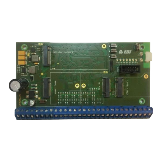
Page 8: System Structure
3. SYSTEM STRUCTURE The CPX300W alarm control panel can be extended with 4 additional modules MOD-GSM-2G / MOD-GSM-3G (including 2 nano SIM holders) - cellular network communication module 2G or 3G, MOD-ETH - wired Ethernet module / MOD-WIFI communication module – wireless Wi-Fi module, ... - Page 9 After pressing the button, the control panel will enter into the unpairing state, which will be signalled by the yellow LED above the button (see item 16). (EXIT) - a button used to exit the wireless devices pairing mode. - Connector for installation of the GSM module. - Connector for installation of the Smart Home module.
-
Page 10: Gsm Module
CELL LED will flash. If a second SIM card is used, it is necessary to configure the control panel accordingly - see chapter "Use a spare SIM card" in the EBS Config 2.0 instruction manual. AVA PRO - Assembly instructions for the CPX300W alarm control panel... -
Page 11: Gsm Antenna
3.2.4. GSM antenna The module is adapted to work with a GSM antenna with an SMA male connector. It is delivered separately as one of the optional system components. The antenna should be installed (glued) to a non-metallic substrate (wood, plastics, glass, etc.) in a vertical position. -
Page 12: Module Installation
- Connector for installation of the module, - Mounting hole for the screw, - Ethernet connection for connecting the network, Fig. 5. View of ETHERNET module boards with descriptions. 3.3.2. Module installation The module should be inserted at an angle of approximately 30° (to minimize the possibility of damage to the connector) into the dedicated connector on the CPX300W motherboard (labelled "ETH / Wi-Fi"... -
Page 13: Technical Parameters
see Fig. 1, item 9) and then screwed with a screw attached to the set (Fig. 6 item 4). NOTE! All installation activities should be carried out with power disconnected. The SMD antenna is build-in the PCB, it means the module cannot be mounted in a metal housing! 3.4.3. -
Page 14: Technical Parameters
3.5.3. Technical parameters Table 5. Technical parameters of the RF433 module. Radio module MIPOT 32001309 Frequency of work 433.92 MHz Main antenna connector (standard) ARK-2 u.FL antenna connector option (interchangeably with ARK-2) Dimensions 29 mm x 35.5 mm 3.5.4. 433 MHz antenna The set includes two types of antennas: Internal wire antenna: Dipole external antenna:... -
Page 15: Smart Home (Z-Wave)
3.6. Smart Home (Z-Wave) Smart Home is a system that allows remote management of both single devices and a whole group of devices located in the building. The system is characterized by perfect adaptation to the user's needs, increases comfort and safety, as well as reduces costs. 3.6.1. -
Page 16: Login To The Network
3.7.1. Login to the network Depending on the module used, the device can transmit data in three ways: wireless via GPRS thanks to the GSM module, wireless via Wi-Fi thanks to the Wi-Fi module, wire by connecting to the Ethernet network thanks to the Ethernet module. When the module was mounted on the CPX300W board and the power supply was turned on, an attempt will be made to log in to the GSM/Ethernet/Wi-Fi network. -
Page 17: Programming
CELL LED will flash. If a second SIM card is used, it is necessary to configure the control panel correctly - see chapter "Use a spare SIM card " in the EBS Config 2.0 instruction manual. AVA PRO - Assembly instructions for the CPX300W alarm control panel... -
Page 18: System Installation
AC to the screw terminals AC, AC. 6. Program the control panel functions. The programming procedure is described in the system programming manual using the EBS Config 2.0 application. 7. Check the system operation again. 4.2. Location of the control panel... -
Page 19: Location Of Wireless Detectors
Fig. 10. Vertical position of the alarm control panel It should also be remembered that the radio waves are dampened by walls and other obstacles. The least dampening walls are made of plasterboard and wood, and the most are made of reinforced concrete containing a metal mesh. -
Page 20: Configuration Of Wired Input Lines
4.4. Configuration of wired input lines All wired input lines are fully configurable and can work as: NO - a line type for connecting detectors with a normally open alarm output (NO). Short circuit will trigger an alarm. NC - a line type for connecting detectors with a normally closed alarm output (NC). - Page 21 Detector No. Detector No. Fig. 12. Configuration of the input line. AVA PRO - Assembly instructions for the CPX300W alarm control panel 21 / 23...
-
Page 22: An Example Of Connecting The Siren Without Battery
4.5. An example of connecting the siren without battery Fig. 13. An example of connecting an internal siren without battery. 4.6. An example of connecting the siren with own battery Fig. 14. An example of connecting an internal siren with own battery. AVA PRO - Assembly instructions for the CPX300W alarm control panel 22 / 23... -
Page 23: Revision History
5. Revision History Date / Revision / Firmware Description 2019.07.12/ w1.0 / 3.0.2 First version of the manual 2019.12.06/ w1.1 / 3.1.0 Description of the MODE button, technical specification updated 2020.02.27/ w1.2 / 3.1.5 Technical specification / firmware version updated, 2020.05.26/ w1.3 / 3.1.7 Update information on the MOD-WIFI module AVA PRO - Assembly instructions for the CPX300W alarm control panel...
Need help?
Do you have a question about the AVA PRO CPX300W and is the answer not in the manual?
Questions and answers