
Related Manuals for EBS CPX230NWB


Summary of Contents for EBS CPX230NWB
- Page 1 Version of the manual: v1.3 Date of issue: 27.07.2018 ALARM CONTROL PANEL CPX230NWB Installation and programming manual Firmware version: 2.10.0 GPRS transmitter configurator version: 1.4.85.3 OSM server version: 1.3.71.036...
- Page 2 DECLARATION OF COMPLIANCE We, EBS Sp. z o.o., declare with full responsibility that the present product meets all requirements provided for in the Directive 1999/5/EC of European Parliament and Council dated 9 March 1999. The copy of the “Declaration of Compliance”...
-
Page 3: Table Of Contents
PERIODIC REPEATING OF WIRELESS DETECTORS LOSS EVENTS ..........36 4.3.12. ACN NUMBERS FOR COMMUNICATION IN THE CONTACT ID FORMAT ........36 4.3.13. ZONES CONFIGURATION ....................... 37 4.3.14. OUTPUTS CONFIGURATION ....................39 CPX230NWB ALARM CONTROL PANEL – INSTALLER MANUAL 3 / 144... - Page 4 AFTER DISARMING DISABLE ALARM HISTORY NOTIFICATION ..........87 6.4.14. ALARM HISTORY NOTIFICATION DISABLING DELAY ............... 88 6.4.15. PREVENT ARMING USING WIRED KEYPAD WHEN INPUTS ARE TRIGGERED OR SABOTAGED ..88 CPX230NWB ALARM CONTROL PANEL – INSTALLER MANUAL 4 / 144...
- Page 5 9.1.5. COMMANDS FOR MANAGING THE WIRELESS DEVICES ............140 9.1.6. COMMANDS FOR MANAGING THE SECURITY SETTINGS ............141 9.2. DICTIONARY OF THE TERMS ....................... 143 10. CHANGE HISTORY ........................144 CPX230NWB ALARM CONTROL PANEL – INSTALLER MANUAL 5 / 144...
-
Page 6: Introduction
1. INTRODUCTION Thank you for choosing EBS alarm control panel. CPX230NWB is a simple, functional alarm control panel integrated with GSM/GPRS/SMS transmitter, intended for small- and medium- sized facilities. The control panel is equipped with 3 outputs, 7 wired (for TEOL configuration up to 14 wired) and up to 32 wireless zones with the possibility to be divided into 2 partitions. -
Page 7: Control Panel Functions
Control of GSM/GPRS connection – automatic restoration of connection with monitoring station or switching to secondary server CONFIGURATION Local, using KP32 keypad or a computer Remote through GPRS, SMS or CSD CPX230NWB ALARM CONTROL PANEL – INSTALLER MANUAL 7 / 144... -
Page 8: Specifications
Lead-acid 12V Low voltage – event threshold: Voltage battery cut off level: below 9V Working temperature: -10ºC to +55ºC Working humidity: 5% to 93% PCB dimensions: 152 x 78 x 30mm CPX230NWB ALARM CONTROL PANEL – INSTALLER MANUAL 8 / 144... -
Page 9: Accessories And Software Applications
Communication Server for Alarm Receiving Center Installers smartphone application for configuration and AVA INSTALL monitoring of the control panel (Android) Mobile Monitoring application for control and monitoring of control panel. (Android, iOS). For Users. CPX230NWB ALARM CONTROL PANEL – INSTALLER MANUAL 9 / 144... -
Page 10: Installation And Wiring
NOTE: If you use more than one keyboard in the system, be sure to address each assignment of the keyboard (see chapter 3.6.4.). 9. Verify the operation of the system and all its components. CPX230NWB ALARM CONTROL PANEL – INSTALLER MANUAL 10 / 144... -
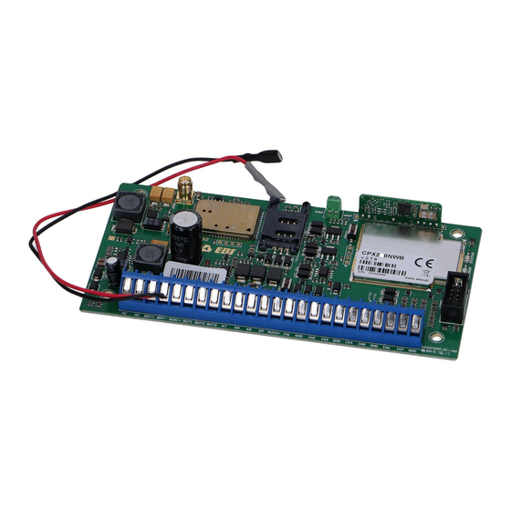
Page 11: Description Of Pcb Elements
The control panel is equipped with integrated GSM/GPRS/SMS transmitter. SIM card with active GPRS transmission is necessary to communicate with the server. The card shall be installed in the slot indicated in the drawing. CPX230NWB ALARM CONTROL PANEL – INSTALLER MANUAL 11 / 144... - Page 12 In option a dedicated plastic OBDNA casing can be ordered (the casing includes appropriate 230VAC/18VAC transformer). 11. Wireless module antenna connector CPX230NWB included two types of antennas: internal and external dipole type. CPX230NWB ALARM CONTROL PANEL – INSTALLER MANUAL 12 / 144...
- Page 13 ANT connector regarding to the color on the endings of the wires. Before screw the antenna, remove plastic element from GND socket. Correct install position for dipole antenna in the attached photo below. CPX230NWB ALARM CONTROL PANEL – INSTALLER MANUAL 13 / 144...
-
Page 14: Description Of Screw Terminals Of The Control Panel
The wireless module is used to receive signals from remote controls and wireless detectors. 3.3. DESCRIPTION OF SCREW TERMINALS OF THE CONTROL PANEL NOTE: Any assembly and installation works shall be carried out with power supply off and battery disconnected. CPX230NWB ALARM CONTROL PANEL – INSTALLER MANUAL 14 / 144... -
Page 15: Configuration Of Wired Input Zones
1 and detector 2 (see drawing 3), while signaling sabotage switch (tamper) open will be common for both detectors. CPX230NWB ALARM CONTROL PANEL – INSTALLER MANUAL 15 / 144... - Page 16 Both resistor types are included in the delivery of the control panel. Various configurations of input zones are presented in the drawing 3. Detector 1 Detector 2 Drawing 3. Configuration of input zones CPX230NWB ALARM CONTROL PANEL – INSTALLER MANUAL 16 / 144...
-
Page 17: Sample Connection Of Signaling Device
3.5. SAMPLE CONNECTION OF SIGNALING DEVICE 3.5.1. Internal signaling device without independent source of power supply Drawing 4. Sample connection of internal signaling device without independent source of power supply CPX230NWB ALARM CONTROL PANEL – INSTALLER MANUAL 17 / 144... -
Page 18: External Signaling Device With Independent Source Of Power Supply
3.5.2. External signaling device with independent source of power supply Drawing 5. Sample connection of external signaling device with independent source of power supply CPX230NWB ALARM CONTROL PANEL – INSTALLER MANUAL 18 / 144... -
Page 19: Kp32 Keypad
2. SLEEP Night mode arming symbol – indicated with diodes B (partition P1) and 2 (partition P2) Blinks slowly: exit time countdown, Blinks quickly: entry time countdown, Lit continuously: partition armed in night mode, CPX230NWB ALARM CONTROL PANEL – INSTALLER MANUAL 19 / 144... - Page 20 A row of diodes used to indicate the status of partition P2 (example: when lit, “3” diode means partition P2 is armed in STAY day mode). 11. Partition 1 (“P1”) The P1 symbol means partition 1, to which diodes from A to H are assigned. CPX230NWB ALARM CONTROL PANEL – INSTALLER MANUAL 20 / 144...
- Page 21 A function button that supports the arming in night mode (SLEEP). 23. Button 9 (sun) A function button that supports the arming in day mode (STAY). 24. Button “*” (flame) CPX230NWB ALARM CONTROL PANEL – INSTALLER MANUAL 21 / 144...
-
Page 22: Keypad Specification
Then carefully take both parts of the casing apart, starting from the casing’s bottom. 3. Mark and drill holes in the wall to install the rear part of the casing. CPX230NWB ALARM CONTROL PANEL – INSTALLER MANUAL 22 / 144... -
Page 23: Addressing Devices Connected To The Keypad Bus
3.7. WIRELESS KEYPAD KP2W The wireless keypad KP2W was designed to work with the hybrid control panel CPX230NWB. There is a possibility to add up to 32 of these keypads, however each of them occupies one of 32 input zones. For instance, if you add 5 keypads KP2W, there leave 27 input zones which can be used for other devices (e.g. -
Page 24: Adding Kp2W To The System
1. Low battery LED (RED) On – battery is low, Off – battery O.K. 2. Data transmission LED (BLUE) Blinks – data transmission in progress Off – no data transmission 3. Keypad buttons CPX230NWB ALARM CONTROL PANEL – INSTALLER MANUAL 24 / 144... -
Page 25: Keypad Specification
125 x 102 x 33 mm Wight without battery: 150 g *Working conditions: test transmission every 15 minutes, keyboard use (arming/disarming) 2 times a day, open door switch closed, working temperature 20°C CPX230NWB ALARM CONTROL PANEL – INSTALLER MANUAL 25 / 144... -
Page 26: Keypad Installation
The connector can be found on the keypad board and labelled 9 in Drawing 7. This sensor in the alarm system CPX230NWB will have assigned the same zone number as the keypad. CPX230NWB ALARM CONTROL PANEL – INSTALLER MANUAL... -
Page 27: Control Panel Location
Reinforced concrete and metal latticed plaster have the greatest attenuation. The drawing 11 shows the signal loss through various different types of materials. (NOTE: the figure is simplified, only for illustration – remember that radio waves propagate multidirectionally). CPX230NWB ALARM CONTROL PANEL – INSTALLER MANUAL 27 / 144... -
Page 28: Wireless Detectors Installation Recommendations
In this way you get the best radio coverage. Additional installation tips describes the drawing 12. Drawing 12. Sensor placement CPX230NWB ALARM CONTROL PANEL – INSTALLER MANUAL 28 / 144... -
Page 29: Service Mode
After pressing the numerical button, the lately entered digit is displayed on a keypad. The way the digits are displayed on a keypad is presented in the table below: CPX230NWB ALARM CONTROL PANEL – INSTALLER MANUAL 29 / 144... -
Page 30: Activation Of Service Mode
After enter the service mode You get permission to configure alarm central. By this commands You can get into some menu sections (more information about procedures You will get in chapters bellow): Installer code change Power loss time report CPX230NWB ALARM CONTROL PANEL – INSTALLER MANUAL 30 / 144... -
Page 31: Installer Code
The function determines time in seconds after which failure is to be reported. The function’s argument is of decimal type. 3 beeps will confirm the successfully entered function. To change /configure the time: CPX230NWB ALARM CONTROL PANEL – INSTALLER MANUAL 31 / 144... -
Page 32: Reset To Default Settings
This option must be enabled in order to comply with EN 50131 standard requirements for Grade 2. CPX230NWB ALARM CONTROL PANEL – INSTALLER MANUAL 32 / 144... -
Page 33: Users Remote Management
(ATS) will appear. When this function is turned on, the Manufacturer recommends that installer code and service code (ATS) code are changed. CPX230NWB ALARM CONTROL PANEL – INSTALLER MANUAL 33 / 144... -
Page 34: Access Code Length
The change will not be accepted, which the keypad will signal with a several seconds long continuous sound. In such a case, one solution is to delete a user or users who have similar codes. CPX230NWB ALARM CONTROL PANEL – INSTALLER MANUAL 34 / 144... -
Page 35: Alarm History Notification Disabling Delay
The time is expressed in hours. The default value is 6 hours, the minimum is 2 and the maximum is 24. NOTE: This option is available since the firmware version 2.8.8 CPX230NWB ALARM CONTROL PANEL – INSTALLER MANUAL 35 / 144... -
Page 36: Switch Off Periodic Repeating Of Wireless Detectors Loss Events
2 – setting or changing the ACN2 number of the partition 2 account button 3 – setting or changing the ACN0 number of the system account number – ACN number – any four hexadecimal characters CPX230NWB ALARM CONTROL PANEL – INSTALLER MANUAL 36 / 144... -
Page 37: Zones Configuration
Entering number 00 will change the parameters for all zones in the system, – number of parameter related to a given zone, - number (or value) of the next parameter. CPX230NWB ALARM CONTROL PANEL – INSTALLER MANUAL 37 / 144... - Page 38 For Y=2 – delay Z in seconds for the zone of selected “delay” response type (DEC type parameter). For other response types the parameter is irrelevant. For Y=3 – operation mode (DEC type parameter), possible values for the parameter o 0 – unused zone CPX230NWB ALARM CONTROL PANEL – INSTALLER MANUAL 38 / 144...
-
Page 39: Outputs Configuration
Codes of output configuration functions are defined as per the following pattern: <XX> <Y> <Z> CPX230NWB ALARM CONTROL PANEL – INSTALLER MANUAL 39 / 144... - Page 40 It is possible to configure the chirp options using following patterns: For Y=3 – chirp signal duration Z in milliseconds; Example: change of chirp signal duration of all zones into 600 milliseconds CPX230NWB ALARM CONTROL PANEL – INSTALLER MANUAL 40 / 144...
-
Page 41: Partitions Configuration
2 – Quiet signaling of time for leaving (during counting the time for leaving, the buzzer in a keypad is not active) CPX230NWB ALARM CONTROL PANEL – INSTALLER MANUAL 41 / 144... - Page 42 A2, B4, C5 and output 1 to belong to partition 2, time for leaving the one to be 45 seconds, alarm time in partition 2 to be 120s and signaling of time for entering and leaving was quiet: ….. CPX230NWB ALARM CONTROL PANEL – INSTALLER MANUAL 42 / 144...
-
Page 43: Wireless Zones Configuration
Once the transmission with the sensor is established, its serial number will be displayed on the keypad (hexadecimal value). If accepted, the sensor will be saved. Example: a) add a wireless sensor B3 (number 11, see the table above): CPX230NWB ALARM CONTROL PANEL – INSTALLER MANUAL 43 / 144... - Page 44 After entering the function PROG LED is blinking, the other LEDs are off. Pressing key deletes all wireless sensors, generating 3 beeps and exit the function. If you press key will exit the function and detectors will not be erased. CPX230NWB ALARM CONTROL PANEL – INSTALLER MANUAL 44 / 144...
-
Page 45: Remote Controllers Configuration
2 – disarm 3 – alarm 4 – silent alarm 5 – enable output 1 6 – enable output 2 7 – enable output 3 8 – disable output 1 CPX230NWB ALARM CONTROL PANEL – INSTALLER MANUAL 45 / 144... -
Page 46: Emergency Buttons
00 – a change of settings of all alarm buttons 01 – FIRE button, activating the fire alarm 02 – HELP button, activating the medical alarm 03 – PANIC button, activating the break-in alarm CPX230NWB ALARM CONTROL PANEL – INSTALLER MANUAL 46 / 144... -
Page 47: Text Messages
CPX230NWB can store up to 10 phone numbers and up to 32 text messages. If, for any reason, the SMS can not be send at the moment, it will be send as soon as the connection with the GSM network is re-established but not later than 1 day after the occurrence of the event triggering SMS send request (text messages get expired and are deleted). - Page 48 ID – index of phone number on the list, possible values: 1 to 10 Example: 1234 GETTELNUM=2 Feedback message GETTELNUM=ID,NUMBER – information about phone description number GETTELNUM:ERROR – command rejected by the system CPX230NWB ALARM CONTROL PANEL – INSTALLER MANUAL 48 / 144...
- Page 49 ID – index of text, possible values: 1 to 32 Example: 1234 GETMESSAGE=30 Feedback message GETMESSAGE=ID,MESSAGE – information about the description contents of text message GETMESSAGE:ERROR – command rejected by the system CPX230NWB ALARM CONTROL PANEL – INSTALLER MANUAL 49 / 144...
- Page 50 Means, that when ARM1 event occurs (partition 1 armed), text message number 6 will be sent to phone numbers with indexes 1,8 and 9. Feedback message SETUSERSMS=EVENT,TELNUM,MSG_ID:OK – command description accepted SETUSERSMS=EVENT,TELNUM,MSG_ID:ERROR – command rejected by the system CPX230NWB ALARM CONTROL PANEL – INSTALLER MANUAL 50 / 144...
- Page 51 PARTITION1,PARTITION2 – default partitions names, they can be changed with the SETNAME command X,Y – partition states, possible values: 0 – disarmed 1 – armed GETARMED:ERROR – command rejected by the system CPX230NWB ALARM CONTROL PANEL – INSTALLER MANUAL 51 / 144...
- Page 52 SETNAME:OK – command accepted description SETNAME:ERROR-PERMISSION - you do not have permission to execute this command SETNAME:ERROR-FORMAT - incorrect format command SETNAME:ERROR-VALUE - incorrectly stated value SETNAME:ERROR-PERMISSION - command rejected; other errors CPX230NWB ALARM CONTROL PANEL – INSTALLER MANUAL 52 / 144...
- Page 53 GETNAME:ERROR-PERMISSION - you do not have permission to execute this command GETNAME:ERROR-FORMAT - wrong format command GETNAME:ERROR-VALUE – wrong value GETNAME:ERROR-PERMISSION - command rejected; other errors CPX230NWB ALARM CONTROL PANEL – INSTALLER MANUAL 53 / 144...
- Page 54 POWER-OK Power failure ended BATTERY-FAIL Battery failure BATTERY-OK Battery failure ended AUX1-FAIL Failure of auxiliary output 1 AUX2-FAIL Failure of auxiliary output 2 AUX1-OK Failure of auxiliary output 1 ended CPX230NWB ALARM CONTROL PANEL – INSTALLER MANUAL 54 / 144...
- Page 55 List of errors sent as feedback messages Alias name Description ERROR-PERMISSION Permission to issue this command was not granted ERROR-FORMAT Wrong command syntax ERROR-VALUE Wrong parameter value ERROR-EMPTY Parameter value missing ERROR Other error CPX230NWB ALARM CONTROL PANEL – INSTALLER MANUAL 55 / 144...
-
Page 56: Configuration Wizard
5.1. PRELIMINARY NOTES The Configuration wizard of GPRS transmitters can be downloaded from www.ebs.pl (login: ebs, password: ebs). Activate the option of installation wizard which leads through the program installation process. By default it will be installed in C:\Program Files\EBS\ directory. -
Page 57: Menu -> File
Menu -> New Opens a new set of parameters. In this option configuration parameters of the equipment can be edited. Select a relevant type of the equipment: CPX230NWB 5.3.1.2. File -> Open If you have a file with recorded settings you can use it for programming another equipment. - Page 58 Click [Add] button to confirm the setting. The connection is saved (and moved to the table). From that moment the program will enable a wire connection with the equipment and allows reading and recording the parameters in the equipment’s memory. CPX230NWB ALARM CONTROL PANEL – INSTALLER MANUAL 58 / 144...
- Page 59 The configuration of that mode requires the activation of File option from Main Menu, and selecting Connection function (or clicking icon on a taskbar) and opening GPRS tab. The following window will be displayed on the screen. CPX230NWB ALARM CONTROL PANEL – INSTALLER MANUAL 59 / 144...
- Page 60 Click [Add] button to confirm the setting. The connection is saved (and moved to the table). From that moment the program will enable a remote connection with the equipment and allows reading and saving the parameters in the equipment’s memory. CPX230NWB ALARM CONTROL PANEL – INSTALLER MANUAL 60 / 144...
-
Page 61: Menu -> Operations
C:\Program Files\EBS\KonfiguratorLX\configs\CPX230NWB_20000\ CPX230NWB_20000 directory contains all files related to programming the CPX230NWB type device of the serial number 20000. Files names contain date and time of the operation and its type (recording/reading). The files are recorded with .cmi extension. - Page 62 For the above select that function. The screen displays the message “Do you really want to overwrite current configuration with default values?” Upon confirmation the connection definition window will be displayed: CPX230NWB ALARM CONTROL PANEL – INSTALLER MANUAL 62 / 144...
-
Page 63: Menu -> Help
Start the configuration wizard and define the options of the equipment (please refer to chapter 6). CPX230NWB ALARM CONTROL PANEL – INSTALLER MANUAL 63 / 144... -
Page 64: Remote Programming
Using the pad of OSM.Server device, indicate with the cursor the correct equipment in ‘Equipment’ tab. Click “Config” option and then indicate “Set configuration” function. A list of parameters will be displayed. CPX230NWB ALARM CONTROL PANEL – INSTALLER MANUAL 64 / 144... - Page 65 (chapter 5.3.1.5.2.). Copy the settings into the memory of the equipment. Close the configuration wizard’s window after you finish the data input. The equipment is ready for data transmission in accordance with new settings. CPX230NWB ALARM CONTROL PANEL – INSTALLER MANUAL 65 / 144...
-
Page 66: Programmable Parameters
GPRS: GPRS transmission (TCP/IP protocol) in standard. In case of any problems with that connection, no remote connection is possible No server connection: no transmission with server, remote communication with a user is possible only via SMS messages CPX230NWB ALARM CONTROL PANEL – INSTALLER MANUAL 66 / 144... -
Page 67: Access Point Parameters
GPRS network. There is a possibility to obtain a private access point. In this case its name will be given by a particular GSM network operator. CPX230NWB ALARM CONTROL PANEL – INSTALLER MANUAL 67 / 144... -
Page 68: Primary Server Parameters
After a defined number of attempts, the equipment will initiate the procedure of connecting with secondary server. The option is active only in case the secondary server parameters were defined. CPX230NWB ALARM CONTROL PANEL – INSTALLER MANUAL 68 / 144... -
Page 69: Secondary Server Parameters
6.1.5.1. Service code It secures the equipment against unauthorized access. It is used for both, equipment programming and for its remote control (in TCP/IP or SMS mode). Default factory setting CPX230NWB ALARM CONTROL PANEL – INSTALLER MANUAL 69 / 144... - Page 70 PUK code (using any GSM phone). Default factory PIN code entered in the equipment is: 1111. CPX230NWB ALARM CONTROL PANEL – INSTALLER MANUAL 70 / 144...
-
Page 71: Transmission
The option can be used for both, GPRS and SMS transmissions. In case encrypted transmission was selected, you can enter own data encryption key (DEK) (256 bits - 0-9 and A-F characters) or use default setting. CPX230NWB ALARM CONTROL PANEL – INSTALLER MANUAL 71 / 144... -
Page 72: Inputs / Outputs
1 and detector 2 (see drawing 3), while signaling sabotage switch (tamper) open will be common for both detectors. Electric diagrams for all configuration types were described in chapter 3.4 Configuration of wired input zones. CPX230NWB ALARM CONTROL PANEL – INSTALLER MANUAL 72 / 144... - Page 73 Violation of this zone will not trigger an alarm when the system is armed in sleep mode. When the system is armed in full mode, the zone will behave like an instant. CPX230NWB ALARM CONTROL PANEL – INSTALLER MANUAL 73 / 144...
- Page 74 Alarm after time for exit When selected, the alarm will be generated if the zone remains violated when the time to exit is up. When deselected, alarm will NOT be generated in above case. CPX230NWB ALARM CONTROL PANEL – INSTALLER MANUAL 74 / 144...
-
Page 75: Wireless Zones (Devices)
'chime zone' is violated, all wired keypads make a beep sound. No report is sent to the monitoring station 6.3.2. Wireless zones (devices) CPX230NWB is capable of storing information up to about 32 wireless inputs: A1 to A8, B1 to B8, C1 to C8, D1 to D8. There are two ways to add detectors (described below). - Page 76 The second way is to directly register the detector in the control panel. To add a wireless detector press the "Register Device" button. CPX230NWB ALARM CONTROL PANEL – INSTALLER MANUAL 76 / 144...
- Page 77 In the new window, select proper connection (serial port number to which CPX230NWB is connected) and zone number for new device. Then enter service code and press “Read” button. A new window pops up with an information about the control panel starting listening for wireless devices.
- Page 78 Now, each detector can be attributed to the type of reaction and assigned with other parameters (in the "Zones" tab), except for sensitivity. CPX230NWB ALARM CONTROL PANEL – INSTALLER MANUAL 78 / 144...
-
Page 79: Partitions
6.3.3.4. Alarm time The parameter defines the time the alarm will be indicated by KP32 keypad. 6.3.3.5. Partition name The parameter allows you to give any name for the partition. CPX230NWB ALARM CONTROL PANEL – INSTALLER MANUAL 79 / 144... - Page 80 Eg. If the auto-arming time is set to 2:30, and time was changed forward from 2:00 to 3:00, the control panel will not arm. Times of arming and disarming can also configure by remote command via GPRS or SMS. CPX230NWB ALARM CONTROL PANEL – INSTALLER MANUAL 80 / 144...
-
Page 81: Outputs
In the case of set time for exit chirp is generated after arming, similarly in the case of the time for entry chirp is generated after disarming. Alarm & chirp – The output is activated when alarm is detected or when arming/disarming. CPX230NWB ALARM CONTROL PANEL – INSTALLER MANUAL 81 / 144... -
Page 82: Remote Controllers
Alarm Control panel. Add Device. Device’s ID and serial number will appear. To accept, press New remote controller has been added in the previously selected row. CPX230NWB ALARM CONTROL PANEL – INSTALLER MANUAL 82 / 144... - Page 83 "Operations" -> "Write"). A window will appear, as in the chapter on wireless detectors. You have to select third checkbox “Write Wireless Devices (only for CPX)” ", enter the service code and press “Write”. CPX230NWB ALARM CONTROL PANEL – INSTALLER MANUAL 83 / 144...
-
Page 84: Emergency Buttons
User can choose which outputs should be turned on in case of the emergency button activation (pressing and holding a button for 3 seconds). Each of the outputs has the reminder of it’s function chosen in the “Outputs” tab. CPX230NWB ALARM CONTROL PANEL – INSTALLER MANUAL 84 / 144... -
Page 85: System Options
Manual, section 6.6 Arming the system with a malfunction). To arm the system press # button. Information on failures and triggering are available after entering with the use of faults memory current input status the wired keypad the user's function: CPX230NWB ALARM CONTROL PANEL – INSTALLER MANUAL 85 / 144... -
Page 86: Access To Alarm And Fault Memory Requires Authorization
(ATS) will appear. When this function is turned on, the Manufacturer recommends the installer’s code and service code (ATS) are changed. CPX230NWB ALARM CONTROL PANEL – INSTALLER MANUAL 86 / 144... -
Page 87: Communication Parameters Lock
24-hour zone will occur, then the fault memory can be turned off by arming and disarming the system (if this option is checked) or by entering the 3# keypad function and deleting the memory. CPX230NWB ALARM CONTROL PANEL – INSTALLER MANUAL 87 / 144... -
Page 88: Alarm History Notification Disabling Delay
The function enables setting the length of the administrator and user codes (the change applies to all users). The code range is from 4 to 7 digits. By default, this value is set to 4. CPX230NWB ALARM CONTROL PANEL – INSTALLER MANUAL 88 / 144... - Page 89 If the code 12345 exists in the database, then after code length is changed to 4 digits, the code will appear as 1234, so the code under duress will be 1235. CPX230NWB ALARM CONTROL PANEL – INSTALLER MANUAL 89 / 144...
-
Page 90: Users
“Cancel” button to withdraw the entered data. Then a question box will appear: After accepting changes please remember to upload the configuration to the device. When uploading a configuration, "Write users" option must be selected in the writing options (second box): CPX230NWB ALARM CONTROL PANEL – INSTALLER MANUAL 90 / 144... -
Page 91: User Categories
1. Administrator – the user with the highest access level. They can both arm, and disarm the system, as well as access and make changes in all user functions presented in CPX230NWB ALARM CONTROL PANEL – INSTALLER MANUAL 91 / 144... -
Page 92: Monitoring
That option allows determining which of available signals generated by the equipment will be transmitted to the monitoring station. NOTE: The “Configuration change” event refers to configuration change via SMS or via GPRS instructions only. 6.6.1. Events CPX230NWB ALARM CONTROL PANEL – INSTALLER MANUAL 92 / 144... -
Page 93: Additional Data
GPRS/SMS. The data may become valuable information about device's work conditions though it may increase amount of bytes sent through GSM network. CPX230NWB ALARM CONTROL PANEL – INSTALLER MANUAL 93 / 144... - Page 94 1 – ACN1 and partition 2 – ACN2. This allows you to determine, which part of the system the signal from. NOTE: This option is available since the firmware version 2.9.0. NOTE: Numbers ACN0, ACN1 and ACN2 consist of four hexadecimal characters. CPX230NWB ALARM CONTROL PANEL – INSTALLER MANUAL 94 / 144...
- Page 95 6.6.2.2.3. Send system events to all accounts Selecting this option will send system events to all accounts, i.e. the system account, partition 1 account and partition 2 account. CPX230NWB ALARM CONTROL PANEL – INSTALLER MANUAL 95 / 144...
-
Page 96: Restrictions
To remove the number from the table, place the cursor in a particular number zone and click [Remove]. “Remove all” option will clear all the numbers from the table. CPX230NWB ALARM CONTROL PANEL – INSTALLER MANUAL 96 / 144... - Page 97 SMS tests to server SMS events sent to server SMS events sent to the user Replies to commands CPX230NWB ALARM CONTROL PANEL – INSTALLER MANUAL 97 / 144...
-
Page 98: Remote Commands
SMS, e.g. in case of a fault. Counter reset: That parameter defines time (in minutes) after which the counter of SMS sent is to be reset. 6.7.2. Remote commands CPX230NWB ALARM CONTROL PANEL – INSTALLER MANUAL 98 / 144... -
Page 99: Sms Notifications
6.8. SMS NOTIFICATIONS 6.8.1. Phones CPX230NWB can notify users about occurrence of certain events by text message. Before sending the message, may occur an additional attempt a voice call (see item 6.8.4. Options). -
Page 100: Messages
In text messages can be used only alphanumeric characters, as well as: ! @ # $ % " < > & * ( ) + : ? ` ; ' = , . / and space. CPX230NWB ALARM CONTROL PANEL – INSTALLER MANUAL 100 / 144... -
Page 101: Events
From now on, whenever this event occurs, a text containing selected message will be send to the selected phone numbers. Before sending the message, may occur an additional attempt a voice call (see item 6.8.4. Options). CPX230NWB ALARM CONTROL PANEL – INSTALLER MANUAL 101 / 144... -
Page 102: Options
In other words, waiting (unsent) SMS messages related to disarmed partition and related to the alarm system will be removed and will not be sent. If the user disarm both partitions, all waiting SMS messages will be removed. CPX230NWB ALARM CONTROL PANEL – INSTALLER MANUAL 102 / 144... -
Page 103: Sms Forward
NOTE: The user is responsible for correct entering the telephone numbers that prevents any turmoil in sending SMS messages. CPX230NWB ALARM CONTROL PANEL – INSTALLER MANUAL 103 / 144... -
Page 104: Link Control
6.9.2. GPRS Activating that function (checking the [Activate] box) allows the access to parameters defining the equipment’s response after losing connection with a server. CPX230NWB ALARM CONTROL PANEL – INSTALLER MANUAL 104 / 144... -
Page 105: Firmware
Open a file with a new firmware (click [Open] to indicate a location of an appropriate file), Select the file transmission method: local. Click [Start] button. The software replacement procedure will be initiated. CPX230NWB ALARM CONTROL PANEL – INSTALLER MANUAL 105 / 144... -
Page 106: Device Monitoring
Device Monitor. This application is installed with the GPRS transmitters configurator by default. CPX230NWB ALARM CONTROL PANEL – INSTALLER MANUAL 106 / 144... - Page 107 PROG cable, SP-PROG/SP-PROG-BT, or MINI-PROG-BT in DEBUG(MONITOR) mode. Then click on the top left corner. A window will appear: after pressed „+” and type, port and name connection defined a new connection can be add. CPX230NWB ALARM CONTROL PANEL – INSTALLER MANUAL 107 / 144...
- Page 108 Serial number o Reaction type, e.g. immediate, 24h tampering o Signal level o status – intact, alarm, tampering or unused (when the detector is not assigned to any partition) CPX230NWB ALARM CONTROL PANEL – INSTALLER MANUAL 108 / 144...
-
Page 109: Events History
“Read” button. After correct reading you will get the access to “Filtering” and “Graphs” functions which allow you a quick diagnosis of the equipment. CPX230NWB ALARM CONTROL PANEL – INSTALLER MANUAL 109 / 144... - Page 110 CPX230NWB ALARM CONTROL PANEL – INSTALLER MANUAL 110 / 144...
-
Page 111: Led Indication
GSM range = 8 GPRS mode GSM range = 6 SMS mode 7.3. TRANSMISSION During data transmission green LED indicates the data sending. LEDs Description ERROR STATUS (green) (red) (yellow) GPRS transmission transmission CPX230NWB ALARM CONTROL PANEL – INSTALLER MANUAL 111 / 144... -
Page 112: Programming
During the equipment’s operation errors can occur. Error is indicated by constant light of red LED and most often it means a communication problem with a modem or SIM card. CPX230NWB ALARM CONTROL PANEL – INSTALLER MANUAL 112 / 144... -
Page 113: Grade 2 Settings
- Battery - Jamming - Keypad output failure - Output AUX1 failure - Output AUX2 failure - Keypad communication lost - Keypad tamper - Keypad power failure - Clock loss CPX230NWB ALARM CONTROL PANEL – INSTALLER MANUAL 113 / 144... -
Page 114: The Behavior Of The System In Compatibility Mode For Grade 2
the codes in the system must be at least 5 characters after entering an invalid code three times, all keypads in the system will be blocked for 90 seconds. CPX230NWB ALARM CONTROL PANEL – INSTALLER MANUAL 114 / 144... -
Page 115: Extras
However, there are parameters, changes to which will be detected only in special circumstances, for example – the server address. If it is changed when the device is online, a restart is needed. When CPX230NWB boots up, it will connect to the newly configured address. -
Page 116: Configuration Parameters
Sets the OSM server address with which the device exchanges data 9.1.1.6. DNS1 Format: DNS1=dns1 Limitations: Valid IPv4 address in numerical form (up to 15 characters), possible to change by ATS only CPX230NWB ALARM CONTROL PANEL – INSTALLER MANUAL 116 / 144... - Page 117 9-bit word: A9 … A2, A1, where A2 input 1 and A3 input 2. EXAMPLE: RLIMIT=6 releases locks from the inputs IN1, IN2 RLIMIT=2 releases locks from the input IN1 CPX230NWB ALARM CONTROL PANEL – INSTALLER MANUAL 117 / 144...
- Page 118 After turning this function off, the system can only be armed if an access code is entered. 9.1.1.13. CLEARMASK Format: CLERMASK=id_typu,indeks,maska Ograniczenia: type_id must be 0, 1 or 2, command can be issued by ATS only CPX230NWB ALARM CONTROL PANEL – INSTALLER MANUAL 118 / 144...
-
Page 119: General Commands
Restarts the GSM modem in the device. This results in breaking a GPRS session and deregistration from the GSM network and re-registration to GSM and GPRS network when you restart the modem. CPX230NWB ALARM CONTROL PANEL – INSTALLER MANUAL 119 / 144... - Page 120 APN – APN name by means of which the GPRS session is compiled UN – APN user name PW –APN password DNS0 –DNS server address 9.1.2.6. Format: OUT=o,s,[time] Limitations: Can be executed only by ATS or administrator CPX230NWB ALARM CONTROL PANEL – INSTALLER MANUAL 120 / 144...
- Page 121 Gets the current status of the device. The returned data are in the following format: zones,partitions,outputs,battery_voltage,voltage_AC,0x0,0x0, blocked_zones where: zones – means the current zone status. It is a bit-vector, where bit 1 CPX230NWB ALARM CONTROL PANEL – INSTALLER MANUAL 121 / 144...
- Page 122 – battery voltage in mV (12000 = 12V). If the battery is not connected, the readings may be incorrect, and be around 9V (9000) voltage_AC – AC voltage at the AC terminals of CPX230NWB (downstream the transformer) in mV (18000 = 18V) blocked_zones –...
- Page 123 CPSETALARMSHOWTIME:EEFORMAT – incorrect command format or delay range Example: CPSETALARMSHOWTIME=20 – 20-second delay time CPSETALARMSHOWTIME= OFF – if the function “After disarming disable the historical alarm signalling” is not active CPX230NWB ALARM CONTROL PANEL – INSTALLER MANUAL 123 / 144...
- Page 124 – it is an ACN account identifier, 0 for ACN0, 1 for ACN1, 2 for ACN2. acn_value – account number expressed in hexadecimal format There can be 3 pairs (acn_id: acn_value) – one for each account. Examples of returned values: CPGETACN:EOK:ALL,0:0x1234,1:0x1235,2:0x1236 CPX230NWB ALARM CONTROL PANEL – INSTALLER MANUAL 124 / 144...
- Page 125 All account numbers (ACN0, ACN1, ACN2) The command returns: CPSETACN:EOK – correct execution CPSETACN: EFORMAT – incorrect command format CPSETACN: ERROR-VALUE – invalid acn_value range CPSETACN: EID – incorrect range of acn_id Example: CPSETACN=ALL,0:0x1234,1:0x1235,2:0x1236 CPSETACN=ACN0,0:1237 CPX230NWB ALARM CONTROL PANEL – INSTALLER MANUAL 125 / 144...
-
Page 126: Commands For Managing The Users
This command only works when sent through an encrypted way and the option “Allow remote user management” is set to active in the Configurator. Possible to execution only by ATS. CPX230NWB ALARM CONTROL PANEL – INSTALLER MANUAL 126 / 144... - Page 127 If the administrator password specified is incorrect CPSETUSERPARTITIONS:ENOT_ALLOWED If the command is sent via open SMS or the configuration does not allow remote management of users CPSETUSERPARTITIONS:EFORMAT If the format of the sent command is incorrect CPX230NWB ALARM CONTROL PANEL – INSTALLER MANUAL 127 / 144...
- Page 128 31 inclusive. The command needs the option “Allow remote user management” to be set to active in the Configurator. Can be executed only by ATS or administrator. If the command is executed by ATS, specify adminPassword CPX230NWB ALARM CONTROL PANEL – INSTALLER MANUAL 128 / 144...
- Page 129 31 inclusive. The command needs the option “Allow remote user management” to be set active in the Configurator. Can be executed only by ATS or administrator. If the command is executed by ATS, specify adminPassword CPX230NWB ALARM CONTROL PANEL – INSTALLER MANUAL 129 / 144...
- Page 130 If the new password is too short or too long or does not consist of digits CPSETADMINPASSWORD: EPERMISIONS If the password can not be changed because it is already used by another user. If you type the current administrator password, the command returns EOK. CPX230NWB ALARM CONTROL PANEL – INSTALLER MANUAL 130 / 144...
- Page 131 If administrator password is incorrect CPGETUSERRIGHTS:ENOT_ALLOWED If the command is sent via open SMS or the configuration does not allow remote management of users CPGETUSERRIGHTS:EFORMAT If the format of the sent command is incorrect CPX230NWB ALARM CONTROL PANEL – INSTALLER MANUAL 131 / 144...
-
Page 132: Commands For Managing The Partitions, Zones And Outputs
1 (counting from 0) means the output 1, bit 2 means the output 2 and bit 3 means the output 3. If the output is enabled, the bit is set. batteryVoltage – battery voltage in mV (12000 = 12V). If the battery is CPX230NWB ALARM CONTROL PANEL – INSTALLER MANUAL 132 / 144... - Page 133 9V (9000) powerSupplyVoltage – AC voltage at AC terminals of CPX230NWB (downstream the transformer) in mV (18000 = 18V). silentAlarms is a bit-vector indicating the quiet alarm memory since the last arming (arming cancels the alarm memory).
- Page 134 1 – configuration memory failure CPGETFAILURES:EPERMISIONS If the specified password is incorrect CPGETFAILURES:ENOT_ALLOWED If the command was sent via open SMS CPDELUSER:EFORMAT If the format of the sent command is incorrect CPX230NWB ALARM CONTROL PANEL – INSTALLER MANUAL 134 / 144...
- Page 135 CPSETPARTITIONS=[STAY/SLEEP]partitions,password:EFORMAT If the data format is incorrect (partitions,password are the command arguments) CPSETPARTITIONS=[STAY/SLEEP]partitions:EPERMISIONS If the user with the specified password does not exist CPX230NWB ALARM CONTROL PANEL – INSTALLER MANUAL 135 / 144...
- Page 136 If an attempt to disarm the armed control panel with the enabled alarm (the alarm is deactivated). CPUNSETPARTITIONS=partitions,password:EFORMAT partitions,password If the data format is incorrect ( are the command arguments) CPUNSETPARTITIONS=partitions:EPERMISIONS If the user with the specified password does not exist CPX230NWB ALARM CONTROL PANEL – INSTALLER MANUAL 136 / 144...
- Page 137 If the format of the sent command is incorrect CPZONESLOCK:EPERMISIONS If the user has not authorization to the proper partition CPZONESLOCK:ENOT_EXISTS If the user with the specified password does not exist CPX230NWB ALARM CONTROL PANEL – INSTALLER MANUAL 137 / 144...
- Page 138 If the format of the sent command is incorrect CPZONESUNLOCK:EPERMISIONS If the user has not authorization to the proper partition CPZONESUNLOCK:ENOT_EXISTS If the user with the specified password does not exist CPX230NWB ALARM CONTROL PANEL – INSTALLER MANUAL 138 / 144...
- Page 139 (counting from 0) means the output 1. CPPARTITIONSGETOUTPUTS:EPERMISIONS If the specified password is incorrect CPPARTITIONSGETOUTPUTS:ENOT_ALLOWED If the command was sent via open SMS CPPARTITIONSGETOUTPUTS:EFORMAT If the format of the sent command is incorrect CPX230NWB ALARM CONTROL PANEL – INSTALLER MANUAL 139 / 144...
-
Page 140: Commands For Managing The Wireless Devices
If the command was sent by an unauthorised user 9.1.5.2. CPDETECTORLOST Format: CPDETECTORLOST=? CPDETECTORLOST=hours Available since: 2.8.8 Limitations: It can be carried out by the ATS and the installer if they have been authorised to perform maintenance services CPX230NWB ALARM CONTROL PANEL – INSTALLER MANUAL 140 / 144... -
Page 141: Commands For Managing The Security Settings
SETATSPWD:ELENGTH – if length of the new password is incorrect – longer than 7 characters, shorter than 4, or contains restricted characters (e.g. space, #, etc.) SETATSPWD:EFORMAT – if the format of the sent command is incorrect CPX230NWB ALARM CONTROL PANEL – INSTALLER MANUAL 141 / 144... - Page 142 This command get the state of “Communication parameters lock” option The command returns: GETCOMMLOCK:0 – the lock is on GETCOMMLOCK:1 – the lock is off GETCOMMLOCK:EPERMISSIONS – if sent with permissions other than CPX230NWB ALARM CONTROL PANEL – INSTALLER MANUAL 142 / 144...
-
Page 143: Dictionary Of The Terms
Alarm history – A list of all past and currently inactive alarms logged in an alarm system. Watchdog – A feature which enables an automatic reaction of an alarm device when its connection to a monitoring station is lost. CPX230NWB ALARM CONTROL PANEL – INSTALLER MANUAL 143 / 144... -
Page 144: Change History
Added a new response type to the zone, information about a 2018.07.27/ v1.3 / 2.10.0 new arming method by using the remote control and the option periodic repeating of wireless detector loss events CPX230NWB ALARM CONTROL PANEL – INSTALLER MANUAL 144 / 144...
Need help?
Do you have a question about the CPX230NWB and is the answer not in the manual?
Questions and answers