
Subscribe to Our Youtube Channel
Related Manuals for AE Conversion INV250-45EU RS485


Summary of Contents for AE Conversion INV250-45EU RS485
- Page 1 Micro-Inverter INV250-45EU RS485 INV250-45EU PLC INV250-45EU INV350-60EU RS485 INV350-60EU PLC INV350-60EU INV500-90EU RS485 INV500-90EU PLC INV500-90EU English...
- Page 2 Assembly and operating instructions INV250-45EU RS485, INV250EU-45 PLC and INV250EU-45 INV350-60EU RS485, INV350EU-60 PLC and INV350EU-60 INV500-90EU RS485, INV500EU-90 PLC and INV500EU-90 Printed in Germany, Copyright by AEconversion GmbH & Co. KG...
-
Page 3: Table Of Contents
Table of contents About this manual Appendix Symbols used Technical data for INV250 Scope Technical data for INV350 Target audience Technical data for INV500 Safety and regulations Overview: Country specific Data General snformation and safety instructions Derating diagrams for INV250 2.1.1 Storage, transport, operation and maintenance Derating diagrams for INV350 2.1.2 Assembly, installation and electrical connection... -
Page 4: About This Manual
These instructions apply to the following micro inverters: - Observe the hazard, warning and safety information provided in these operating and • INV250-45EU installation instructions. • INV250-45EU RS485 • INV250-45EU PLC • INV350-60EU - Do not under any circumstances tamper with •... -
Page 5: Ce Mark
- If you mount the inverters at a great height, avoid 3.0 Notes on liability, warranty and service possible risks of falling. The following information relates to liability, warranty and - Do not insert any electrically conductive parts into the plugs and sockets! Tools must be dry. service. -
Page 6: Service
A power control is integrated in the inverter depending on the 3.3 Service temperature. The following diagrams show the maximum input We have already placed special emphasis on the quality and power of the inverter versus the ambient temperature and air durability of the inverter during the development phase. -
Page 7: Scope Of Delivery
The following monitoring and protection concepts are INV350-60EU integrated in the AEconversion units of the validity range: INV500-90EU • Overvoltage arresters / varistors to protect the power INV250-45EU RS485 semiconductors • Temperature monitoring INV350-60EU RS485 • EMC filters to protect the inverter from high-frequency mains... -
Page 8: Operating Conditions
Activate output via fibre optics: • Switch off AC For INV250-45EU this voltage is 20 V. • LED signals the start of the output sequence by „ON“ for 5 sec. For INV350-60EU this voltage is 20 V. • LED outputs the data as a pulse pattern (duration approx. 50 For INV350-90EU this voltage is 40 V. -
Page 9: Installation On Pv-Racking
Due to the PV generator voltage, a higher current flows on the DC side than on the AC side. As a result, with the same cable cross-sections and lengths, the losses on the DC side would be higher. For this reason, it makes sense to place the inverter close to the PV module. -
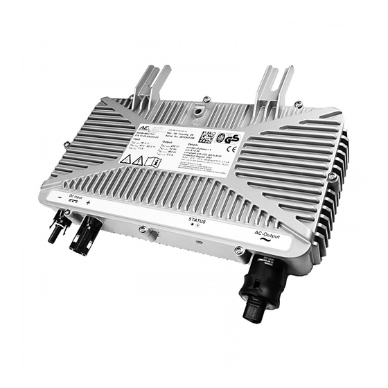
Page 10: Overview Of Connections
To achieve protection class IP65/IP67, all plugs and sockets must be plugged in with the respective mating plugs or closed with protective caps. DC connector PV- If the line resistance is high, i.e. if the line length is long on DC connector PV+ the AC side, the voltage at the mains terminals of the inverter Climatic membrane... -
Page 11: Ac Connections Of The Inverter Plc / Nocom
8.3 DC connection Dangerous touch voltages can occur during the installation of the photovoltaic system. To ensure your safety, please make sure that the DC connection cables of the PV generator do not come 8.2.1 AC Connection of Powerline / NOCOM devices into contact with the earth potential. -
Page 12: Communication Setup
inverter. 8.4.1 RS485 communication Please note the following for the RS485 variant of the inverter: To enable remote monitoring of your photovoltaic system, the inverters also have two RS485 interfaces. The RS485 interface is used for remote communication. The RS485 communication can be established over a distance of up to 1000m. -
Page 13: Without Communication
• Description of the protective device with information on type, circuit, make and function • Description of the inverter or • Declaration of conformity and clearance certificate • Information on the short-circuit resistance of the switching devices 10.0 Switching off the inverter You must switch off the inverter for adjustment, maintenance and repair work. -
Page 14: Further Information
Standard Display inverter Meaning 12.3 Laws, regulations and technical rules given by When constructing solar installations, the laws and regulations utility applicable to the respective country at state, federal and company European or international level must be observed. 100% External limitation The maximum possible 100% power is fed in. -
Page 15: Technical Data For Inv250
INV250-45 Micro Inverter Description The AEconversion micro inverter INV250-45 converts the generated energy into grid-compliant alternating current. For this purpose, the INV250-45 is directly connected to one or two PV modules. The individual conversion enables the optimal utilization of solar energy. The INV250-45 micro inverter works with modules up to 400W with a maximum PV input voltage of 45V. -
Page 16: Technical Data For Inv350
INV350-60 Micro Inverter Description The AEconversion micro inverter INV350-60 converts the generated energy into grid-compliant alternating current. For this purpose, the INV350-60 is directly connected to one or two PV modules. The individual conversion enables optimal utilisation of the solar energy. The INV350-60 micro-inverter operates up to a power of 500W with a maximum PV input voltage of 60V. -
Page 17: Technical Data For Inv500
INV350-90 Micro Inverter Description The AEconversion micro inverter INV350-90 converts the generated energy into grid-compliant alternating current. For this purpose, the INV350-90 is directly connected to one or two PV modules. The individual conversion enables optimal utilisation of the solar energy. The INV350-90 micro-inverter operates up to a power of 500W with a maximum PV input voltage of 90V. - Page 18 INV500-90 Micro Inverter Description The AEconversion micro inverter INV500-90 converts the generated energy into grid-compliant alternating current. For this purpose, the INV500-90 is directly connected to one or two PV modules. The individual conversion enables optimal utilisation of the solar energy. The INV500-90 micro-inverter operates up to a power of 700W with a maximum PV input voltage of 90V.
-
Page 19: Overview: Country Specific Data
Overview: Country-specific data 250W / 350W / 500W 02.2020 INV250 / INV350 / INV500... -
Page 20: Derating Diagrams For Inv250
Derating diagrams for INV250 Derating P pv / I pv Derating Ppv / T ambient 0m/s Wind speed Derating Ppv / T ambient 0,1 m/s Wind speed INV250 / INV350 / INV500 02.2020... -
Page 21: Derating Diagrams For Inv500
Derating diagrams for INV350-60 Derating P pv / I pv Derating Ppv / T ambient 0m/s Wind speed Leistungsreduzierung Ppv / T ambient 0,1 m/s Wind speed 02.2020 INV250 / INV350 / INV500... - Page 22 Derating diagrams for INV350-90 and INV500-90 Derating P pv / I pv Derating Ppv / T ambient 0m/s Wind speed Derating Ppv / T ambient 0,1 m/s Wind speed INV250 / INV350 / INV500 02.2020...
-
Page 23: Declaration Of Ce-Conformity
Derating diagrams for INV350-90 and INV500-90 Derating P pv / U ac 02.2020 INV250 / INV350 / INV500... - Page 24 Konformitätserklärung INV250 / INV350 / INV500 02.2020...
- Page 25 AEconversion GmbH & Co. KG • An der Helle 26 • 59495 Bad Sassendorf • Germany Telefon +49 (0) 2927 9194-10 • Telefax +49 (0) 2927 9194-50 • www.aeconversion.de 02.2020 INV250 / INV350 / INV500...
Need help?
Do you have a question about the INV250-45EU RS485 and is the answer not in the manual?
Questions and answers