Table of Contents
Advertisement
Quick Links
Advertisement
Table of Contents

Related Manuals for AE Conversion INV315-50EU


Summary of Contents for AE Conversion INV315-50EU
- Page 1 Micro-Inverter INV315-50EU English...
- Page 2 Assembly and operating instructions INV315-50EU Printed in Germany, Copyright by AEconversion GmbH & Co. KG...
-
Page 3: Table Of Contents
Initial operation Registring with with utility company Acceptance of the plant by the utility company 10.0 Switching off the inverter 11.0 External limiting 12.0 further information 12.1 Disposal 12.2 Care 12.3 Laws, regulations and technical rules 13.0 Technical data 11.2019 INV315-50EU... -
Page 4: About This Manual 4 Appendix
The following warnings must be observed for assembly, electrician. installation and electrical connection. - The device must be mounted in accordance with the safety regulations (e.g. DIN, VDE) and all other relevant state or local regulations. INV315-50EU 11.2019... -
Page 5: Ce Mark
Under „Caution hot surface“ it is pointed out that • Transport damage surfaces of devices could be hot and there is a risk • Use of non-original PV mating plugs and sockets from the of burns. HELIOS H4 product series by Amphenol 11.2019 INV315-50EU... -
Page 6: Service
Each inverter can be mounted on the mounting rack underneath temperature and the air velocity around the inverter influence the PV modules, but it is recommended to have a place where its performance. emergency service work can be easily carried out. INV315-50EU 11.2019... -
Page 7: Scope Of Delivery
Height Sequence ends: 2 sec. „AUS“ [mm] [mm] [mm] INV315-50EU Insulation measurement on the PV side: In feed-in operation, a too low insulation resistance between PV and AC side is signalled with a fast flashing. For this purpose, INV315-50EU the flashing frequency for displaying the feed-in power is Without mounting interrupted every approx. -
Page 8: Operating Conditions
• Ensure a minimum distance of 20 mm between the upper - Uo (-15°C) < max. input voltage: 50 V and -15°C for an INV315-50EU / RF edge of the roof and the underside of the inverter. We also recommend a distance of 25 mm between the back of the PV The open-circuit voltage of the connected PV generator must module and the top edge of the inverter. -
Page 9: Installation On Pv-Racking
8.0 Connections The following sections describe how to make the AC, DC and data transmission connections. When making the connections, the standards and regulations must be followed, as well as the safety instructions contained in these operating instructions. 11.2019 INV315-50EU... -
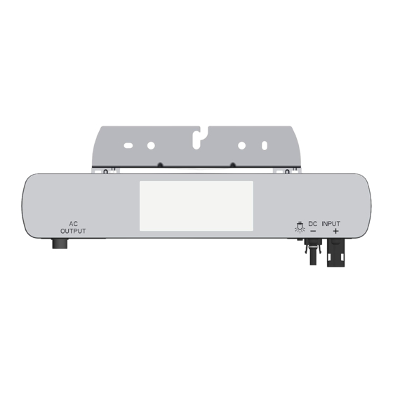
Page 10: Overview Of Connections
AC side, the voltage at the mains terminals of the inverter increases during feed-in operation. This voltage is measured by the inverter. If the voltage at the grid terminals exceeds the limit for grid overvoltage, the inverter switches off due to grid overvoltage. INV315-50EU 11.2019... -
Page 11: Ac-Connection Of Many Devices
This step is carried out for all remaining PV modules with the scope of delivery of the micro inverter. inverter attached below, without exceeding the maximum number of inverters in the AC circuit. (See accessories overview for ordering information) The exact handling of the DC connections is as follows: 11.2019 INV315-50EU... -
Page 12: Communication Setup
The DC cabling of an inverter with a PV module looks conceptually as follows: The AEconversion RF gateway is needed to convert the received data to standard RS-485. For more information about the AEconversion RF gateway, see the separate gateway manual. INV315-50EU 11.2019... -
Page 13: Without Communication
You must switch off the inverter for adjustment, maintenance and repair work. Proceed as follows: • Switch off the mains voltage (deactivate the external fuse elements). • After switching off, check that there is no voltage • Follow the local regulations for work on electrical installations. 11.2019 INV315-50EU... -
Page 14: Further Information
Comply with the environmentally relevant requirements regarding recovery, reuse and disposal of operating materials and components in accordance with DIN EN 378. 12.2 Care Keep the surface of the inverter free of dust and dirt. INV315-50EU 11.2019... - Page 15 · Communication Version: smart RF communication · Cooling: natural convection · Safety class: Class I · Enclosure material: aluminum · Topology: Transformer/galvanically isolated · Protection Degree: IP65 ( iP67 ) & NEMA4 · integrated safety features AEconversion GmbH & Co. KG www.aeconversion.de 11.2019 INV315-50EU...
-
Page 16: Scope 4 Derating Diagrams
P pv 25V 200 W P pv 40V 150 W 100 W -15 °C -10 °C -5 °C 0 °C 5 °C 10 °C 15 °C 20 °C 25 °C 30 °C T amb @ 0,1m/s wind speed INV315-50EU 11.2019... -
Page 17: Target Audience 4 Declaration Of Ce-Conformity
Produktbezeichnungen: Name of Product: Micro-Inverter Art. Nr. / Part No. INV315-50EU 11-05-600012-XX Further models of this family: Die bezeichneten Produkte stimmen mit den Vorschriften folgender europäischer Richtlinien überein: The indicated products are in correspondence with the following regulations of European Council:... -
Page 18: Safety And Regulations 4 Overview: Country Specific Data
Latvia Bulgaria Cyprus Sweden Switzerland Poland Czech Republic Slowakia Finnland Albany Ireland Slovenia Malta Croatia Romania Kosovo Israel Australia Tunisia Barbados Chile South Africa Iran China Kazakhstan India Tansania Mauritius Sri Lanka Saudi Arabia (50Hz) Japan (50Hz) Ghana INV315-50EU 11.2019... - Page 19 AEconversion GmbH & Co. KG • An der Helle 26 • 59505 Bad Sassendorf • Germany Telefon +49 (0) 2927 9194-10 • Telefax +49 (0) 2927 9194-50 • www.aeconversion.de 11.2019 INV315-50EU...
Need help?
Do you have a question about the INV315-50EU and is the answer not in the manual?
Questions and answers