Table of Contents
Advertisement
Quick Links
Advertisement
Table of Contents

Subscribe to Our Youtube Channel
Related Manuals for CenterVue drs plus


Summary of Contents for CenterVue drs plus
- Page 1 Operating Manual DRSplus – Operating Manual 1/58...
- Page 2 December 14, 2019 Revision Number: Reference software version: Manufacturer: CenterVue S.p.A. Via San Marco 9h, 35129 Padova – ITALY Tel. +39 049 501 8399 Fax +39 049 501 8398 The information in this manual are correct at the date of issue of the manual. The device configuration can change as product improvement are incorporated and this manual may not exactly depict your device.
-
Page 3: Table Of Contents
CONTENTS Introduction ..............................5 Symbols ................................6 Symbols used on the device ........................6 Other symbols found in this manual ..................... 6 Product description ............................8 Labels ................................11 WARNINGS AND PRECAUTIONS ........................12 Notes for the operator ..........................14 Definitions ............................ - Page 4 14.3 Restore ..............................44 14.4 Reset ..............................45 14.5 Licenses ............................... 45 14.6 Update ..............................46 14.7 More ..............................46 14.8 Demo dataset ............................47 14.9 Optical head position .......................... 47 15. Power-off ..............................48 16. Cleaning ............................... 49 17. Maintenance ..............................50 18.
-
Page 5: Introduction
1. Introduction Congratulations for choosing and its color confocal retinal imaging capabilities. plus is intended for the acquisition of colored images of the retina without the use of a plus mydriatic agent. More specifically, the provides colored images of the retina with a field of plus view of 45°... -
Page 6: Symbols
2. Symbols 2.1 Symbols used on the device The meaning of the symbols adopted in the device labels is as follows: Symbol Explanation Information about the Manufacturer. Manufacturing date (year/week). Electrical and electronic waste is destined for separate recycling. Refer to the Operating Manual. CE mark: the device complies with the essential requirements of the European Medical Devices Directive 93/42/EC. - Page 7 General Warning, read carefully. DRSplus – Operating Manual 7/58...
-
Page 8: Product Description
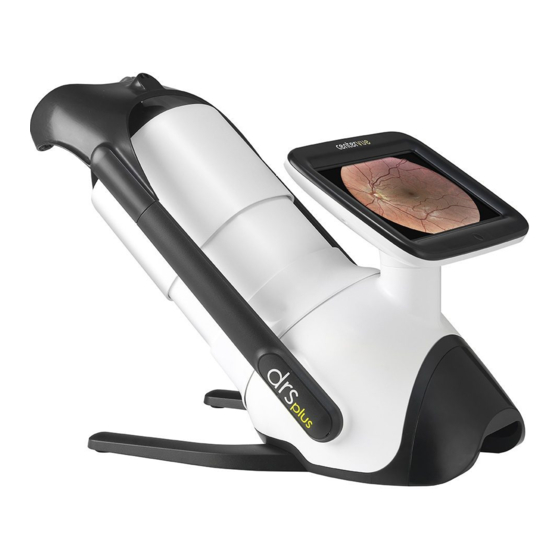
3. Product description consists of: plus ❖ The device (with a lens cap for shipping only) (Fig. 1); ❖ Cables protection shell (Fig. 2); ❖ Device stand (Fig. 3); ❖ Headrest with silicon cushion (Fig. 4); ❖ External power supply (Fig. 5) which includes a country-specific power cable. Fig. - Page 9 Headrest Touch screen Patient side Operator side Back panel (with shell) Fig. 6 – plus Power supply connector USB ports Ethernet port DisplayPort (version 1.0) Device power status Power button Fig. 7 – Back Panel DRSplus – Operating Manual 9/58...
- Page 10 can be equipped with: plus ❖ External fixation light (Fig. 8); ❖ Prismatic goggles for stereo view (Fig. 9). Fig. 8 – External fixation light Fig. 9 - Stereo goggles is provided with: plus ❖ This operating manual; ❖ Contents list; ❖...
-
Page 11: Labels
4. Labels The device label is located on the back side of the display, as shown in Fig. 10 Fig. 10 – Device label DRSplus – Operating Manual 11/58... -
Page 12: Warnings And Precautions
❖ Do not use the device if the covers or other parts of the device have been removed. ❖ Only technicians authorized by CenterVue may service the . CenterVue plus cannot be held responsible for the device safety should... - Page 13 ❖ needs to be operated in the following environmental conditions: plus o Temperature: +10 °C to +35 °C o Humidity (max): 90% not condensing ❖ needs to be stored in the following environmental conditions: plus o Temperature: -10 °C to +60 °C o Humidity (max): 90% not condensing ❖...
-
Page 14: Notes For The Operator
6. Notes for the operator This section provides basic information for operators. No specific skills are required to use the plus . However, operators must receive the minimum training in the use of the device. The plus acquisition of images using the does not involve any risks. -
Page 15: Preparation Of Device
7. Preparation of device This section explains how to set up the for use. plus 7.1 First usage Read carefully the chapter 5 before proceeding to the device operation. To prepare for the first usage: plus ❖ Take the device out of its shipping box and place it onto a suitable table; ❖... -
Page 16: Initial Configuration Wizard
Fig. 12 – Back panel with cables protection shell 7.2 Initial configuration wizard Turn on the device by pressing the power switch button: upon the first power on of the device, the initial Configuration Wizard will be (Fig. 13). Use the button located near the top-right corner of the screen to temporarily skip the Configuration Wizard and go straight to the login screen. - Page 17 In the following step it is possible to set the current time-zone (Fig. 14). Fig. 14 – Configuration Wizard: setting of the local time-zone In the following step it is possible to set the current date and time and configure their format (Fig. 15). Fig.
-
Page 18: Login
Fig. 16 – Configuration Wizard: creation of the System Administrator account In the following screen (Fig. 17) it is possible to create another account (Operator account), by following the same rules and constraints described for the Administration account. Fig. 17 – Configuration Wizard: creation of user accounts 7.3 Login Turn on the device by pressing the power switch button (Fig. -
Page 19: Patient List
Fig. 18 –Login screen 7.4 Patient list Upon the login, the Patient List will be shown (Fig. 19). It includes the following data, for each patient, from left to right: ❖ Thumbnails of the last two images acquired for that patient. The total number of images acquired for that patient is superimposed above the thumbnail, for the left and right eye respectively;... -
Page 20: Navigation Bar
7.5 Navigation Bar Upon the login, the Navigation Bar shown in Fig. 20 is found on many screens. At the center of the Navigation Bar the current username, date and time are found. Fig. 20 – Navigation Bar The Navigation Bar functionalities follows: Function Command Browse to the Patient List... -
Page 21: Preparation Of The Patient
8. Preparation of the patient This paragraph is dedicated to the patient preparation before taking pictures with the plus There are no specific restrictions based on the typology of patients that can be examined with plus is a non-mydriatic medical device, therefore it is not mandatory to dilate patients before taking plus pictures. -
Page 22: Acquisition Of Retinal Images
9. Acquisition of retinal images This paragraph explains how to acquire high quality retinal images using plus To start the acquisition process, it is necessary to select the desired patient in the Patient List. To do so, in the Patient List screen: ❖... -
Page 23: Configuration Of Exam Parameters
9.1 Configuration of Exam Parameters To configure the examination, the following parameters can be set (see Fig. 22): ❖ Eye: o OD = right eye, o OS = left eye, o OU = both eyes (default option); ❖ Exam modality: o default = acquire a retinal picture, o EXTERNAL EYE = acquire a picture of the external eye surface (see §0), o STEREO = acquire a couple of retinal images for stereo review (see §9.5);... -
Page 24: Automatic Acquisition Of Images
h. SUPERIOR-NASAL: centered approx. 12° superiorly and 7° nasally to the foveal pit; INFERIOR-TEMPORAL: centered approx. 12° inferiorly and 7° temporally to the foveal pit; INFERIOR-NASAL: centered approx. 12° inferiorly and 7° nasally to the foveal pit. ❖ Give the patient detailed information about the device operation before placing the patient on the device. -
Page 25: Fast" Exam
Information Position on the screen Estimated pupil size: when yellow, indicates that the pupil size is Under the graphics of the eye below the minimum suggested value position Acquisition status of every field set for the current examination Under the estimated pupil (pending, acquiring, completed) size Live image of the retina, acquired using infrared light... -
Page 26: External Eye" Examination
Fig. 24 – Exam configuration screen (“Fast exam” mode) After the acquisition of the images, the Patient Detail screen will be shown, where the operator can edit any of the patient information. 9.4 “External eye” examination When this modality is set, the will automatically acquire an image of the external surface of plus the eye (see Fig. -
Page 27: Patients Database
10. Patients Database 10.1 Adding a new patient Open the “New Patient” dialog by pressing the button in the Patient List (Fig. 26). Enter Surname and Name (mandatory fields) for the new patient; enter additional fields if available: ID, Birthdate, Gender and Notes. Press SAVE to save the new patient or CANCEL to cancel the operation. -
Page 28: Deletion Of Patients
or keep pressed the patient row until the selection appears. 10.4 Deletion of patients Select the patients to be deleted and click the “Delete” button on the right panel → 10.5 Export of all patients’ images Select the patients whose images are to be exported and click the “Export” button in the right panel →... -
Page 29: Image Review
11. Image review 11.1 Patient Details screen Upon the acquisition of images, will show the Patient Details screen (Fig. 28), which includes plus patient information and all of the images acquired. Patient information shown: Information Position on the screen Patient information Top left box List of dates when the patient was examined. - Page 30 Function Command Creation of a new mosaic Flicker images Modify patient’s information Delete the current patient Export all of the images of the patient Multiple selection of images Side-by-side comparison of two images Export of all of the patient’s images Print images 3, 4 Delete images...
-
Page 31: Image Review
11.2 Image review The image review screen (Fig. 29) is used to review a single image at full resolution. Fig. 29 – Single image review screen Available functionalities Function Command buttons located on the Browse to the previous / next image left / right edge of the screen Browse back to the patient details screen button, top right... -
Page 32: Side-By-Side Image Review
11.3 Side-by-side image review The “side-by-side” screen (Fig. 31) permits the operator to quickly compare any couple of images selected from the Patient details screen. Images are shown next to each other. Fig. 31 – Side-by-side screen Available functionalities Function Command Enable / Disable the zoom and pan synchronization (any zoom and pan operation done on an image will immediately will replicated on... -
Page 33: Visual Flickering Of Images
11.4 Visual flickering of images The flickering screen (Fig. 33) gives the possibility to select any couple of images of the current patient, and shows the fast alternation of them. Prior the visualization, the images are registered one to the other in order to ease the clinician to review them having all of the image features accurately overlapped. - Page 34 Fig. 34 – Selection of images for mosaic will generate the mosaic automatically and will save it as a new image, available in the plus Patient Details screen. Fig. 35 – A mosaic The creation of a new mosaic is possible only under certain conditions: a) The selected retinal fields belong to the same eye;...
-
Page 35: Remote Viewer
A mosaic of retinal images can show visual artifacts (e.g. duplicated retinal vessels or non-contiguous retinal vessels) in the areas where two images are stitched together. These artifacts can be easily recognized by looking at the original images. 11.6 Remote Viewer All of the patient database and the images stored into the memory can be remotely reviewed plus... -
Page 36: Exporting Images
12. Exporting images offers extreme flexibility in exporting images. In detail, it is possible to: plus ❖ simultaneously export all images of one or more patients (§10.5, §11.1); ❖ export a single image (§0); ❖ configure (§13.6) one or more destinations, including USB and network drives; ❖... -
Page 37: Configuring The Device
13. Configuring the device To access the configuration screen, click on the icon → in the toolbar and then Settings in the drop-down menu. The menu on the left allows access to various configuration panels, described below. Some configuration panels are accessible or restricted, according to the user level. 13.1 Account The “Account”... -
Page 38: Network
Fig. 38 - “Users” panel ❖ The user name must contain at least 4 characters ❖ The password must contain at least 6 characters 13.3 Network This panel (Fig. 39) makes it possible to configure the parameters required for the network connection and specify the primary network using the selector. -
Page 39: Date And Time
Function Command Enable / disable Wi-Fi interface Disconnect the device from the current Wi-Fi network Scan for available Wi-Fi networks To check the network connection status, click on the icon in the top bar (Fig. 41). Fig. 41 – Example of wired and Wi-Fi network connection status 13.4 Date and time This panel (Fig. -
Page 40: Export
When enabling “HTTPS” the device will use a self-signed HTTPS certificate that must be accepted into your browser in order to dismiss the standard warning issued by all browsers. Fig. 43 - "Security" panel 13.6 Export This panel (Fig. 44, Fig. 45) allows you to configure the parameters relating to the export function. Fig. -
Page 41: Printers
Fig. 45 – Configuration of export destination 13.7 Printers This panel (Fig. 46) allows you to configure the printing subsystem. Refer to the on-line documentation for details of how to configure the CUPS printing system. Fig. 46 - "Printers" panel DRSplus –... -
Page 42: Utilities
Function Command Open a Remote Assistance (RA) session Upload diagnostic data to a CenterVue server Export diagnostic data to USB Fig. 47 – Assistance Utilities The current status of the Remote Assistance session is always available through the “service”... -
Page 43: Backup
14.2 Backup This panel (Fig. 48) provides the utility to perform the backup of the patient data stored in the on- board disk. Fig. 48 – “Backup” panel Data can be backed up on an external, USB-connected memory device (flash memory or disk) or a remote network destination. -
Page 44: Restore
Function Command Activation of automatic backup utility and setting of frequency, day and time of execution Configuration of storage units in networks on which backup is performed automatically (= destination) Configuration of external storage units (USB keys and discs) on which backup is performed automatically (= destination) 14.3 Restore This panel (Fig. -
Page 45: Reset
Fig. 49 – “Restore” panel 14.4 Reset This panel (Fig. 50) can only be accessed by an Administrator and allows to reset the device. Function Command Deletion of all patients and examination data On resetting to factory settings, all data will be erased and all settings returned to initial values. -
Page 46: Update
Fig. 51 - "License" panel 14.6 Update This panel (Fig. 52) provides the utility to install software updates and upgrades. Access to this panel is limited to the Administrator user. The installation package should be saved on the top folder of a USB flash memory which then must be plugged into one of the three USB ports. -
Page 47: Demo Dataset
Fig. 53 - "More" panel 14.8 Demo dataset Once the demo dataset is enabled, the patient list will be populated with a small number of dummy patient records each containing a few sample images intended to showcase the quality of the images that can be acquired with the plus The dummy patients cannot be edited. -
Page 48: Power-Off
15. Power-off ❖ To power off the device click on the “power” icon near the top- right corner of the screen → ❖ A menu will open: select the “Logout” option to close the current session → ❖ or select “Reboot” to restart the device → ❖... -
Page 49: Cleaning
16. Cleaning This paragraph explains how to clean the device. The device must be powered off, and the power cord shall be disconnected from mains. The front lens should be cleaned using a small hand pump air blower to blow away dust. If the lens is very dirty, for instance due to the presence of fingerprints or other impurities, the front lens should be cleaned using photographic cleaning paper or a very clean microfiber cloth and a suitable lens cleaning fluid. -
Page 50: Maintenance
17. Maintenance All maintenance operations must be carried out exclusively by personnel authorized by CenterVue. Maintenance frequency recommended by CenterVue: ❖ Safety electric tests (according to IEC 60601-1): once a year. ❖ Comprehensive system verification: every two years. Inquire with your local distributor or Authorized Service Center for service contracts and warranty extensions. -
Page 51: Electromagnetic Compatibility
18. Electromagnetic Compatibility This device complies with the requirements of Class A as defined by the IEC 60601-1-2 standard. This device has been tested and found to comply with the limits for medical devices contained in IEC60601-1-2 and Medical Device Directive 93/42/EEC. These limits are intended to provide reasonable protection against harmful interference in a typical medical installation. -
Page 52: Guidance And Manufacturer Declaration - Electromagnetic Immunity
uses RF energy for its internal function. plus RF emissions Therefore, its RF emissions are very low and not Group 1 CISPR 11 likely to cause any interference in nearby electronic equipment. RF emissions Warning: The EMISSIONS characteristics of this Class A CISPR 11 equipment make it suitable for use in industrial areas... - Page 53 for 5s ) for 5s intervals. Power frequency magnetic fields should Power frequency be at levels (50/60 Hz) magnetic 30 A/m 30 A/m characteristic of a field IEC 61000-4-8 typical location in a typical commercial or hospital environment. NOTE U is the a.c.
-
Page 54: Immunity Tests Performance Criteria
Table 3 – Electromagnetic Immunity (ISO 60601-1-2:2007 5.2.2.2) IEC60601 test Compliance Immunity Test Electromagnetic environment guidance level Level Portable and mobile RF equipment should be used no closer to any part of , including cables, plus than the recommended separation distance calculated from the equation applicable to the frequency of the transmitter. -
Page 55: Wi-Fi Specifications
is intended for use in an electromagnetic environment in which radiated RF disturbances are plus controlled. The customer or the user of can help prevent electromagnetic interference by plus maintaining a minimum distance between portable and mobile RF communications equipment (transmitters) and as recommended below, according to the maximum output power of the plus... -
Page 56: Fcc (Usa) And Ic (Canada) Radio Certification
Authentication WPA and WPA2, 802.1X (EAP-TLS, TTLS, PEAP, LEAP, EAP-FAST), EAP-SIM, EAP-AKA Authentication Protocols PAP, CHAP, TLS, GTC, MS-CHAP*, MS-CHAPv2 Encryption 64-bit and 128-bit WEP, AES-CCMP, TKIP Wi-Fi Direct Encryption and WPA2, AES-CCMP Authentication Product Safety UL, C-UL, CB (IEC 60950-1) Management Frame 802.11w (WFA- Protected Management Frames) -
Page 57: Technical Specifications
20. Disposal is made of different materials, such as plastics, aluminum, electronic parts. In case of plus instrument disposal, please separate the various materials and follow the laws and regulations regarding disposal or recycling for each material effective in your own country. 20.1 Separate collection for electrical and electronic equipment The European Directive 2012/19/EU establishes separate collection for Waste of Electrical and Electronic Equipment (WEEE).
Need help?
Do you have a question about the drs plus and is the answer not in the manual?
Questions and answers