Table of Contents
Advertisement
Quick Links
Advertisement
Table of Contents

Subscribe to Our Youtube Channel
Related Manuals for R&S ZC Series


Summary of Contents for R&S ZC Series
- Page 1 ® R&S ZCxxx Converters Getting Started (;ÛÁÆ2) 1177515602 Version 05...
- Page 2 ® This manual describes the R&S ZCxxx family of frequency converters, jointly manufactured by Rohde & Schwarz and RPG-Radiometer Physics, a Rohde & Schwarz company: ● R&S ® ZC75, millimeterwave converter WR15 (order no. 1323.8259.02) ● R&S ® ZC90, millimeterwave converter WR12 (order no. 1323.7600.02) ●...
-
Page 3: Table Of Contents
® Contents R&S ZCxxx Contents 1 Safety and regulatory information........5 1.1 Labels on the product................5 1.2 Warning messages in the documentation.......... 6 1.3 Korea certification class B..............6 2 Key features................7 3 Preparing for use..............9 3.1 Unpacking and checking..............9 3.2 Choosing the operating site.............. - Page 4 ® Contents R&S ZCxxx 6.2 Configuration and measurement steps..........27 6.3 Configuring the converter setup............27 6.4 Establishing the RF connections............30 6.5 Scalar power calibration and leveling (optional)......30 6.6 System error correction..............34 6.7 Measurement..................34 6.8 Additional information................35 7 Maintenance and disposal..........
-
Page 5: Safety And Regulatory Information
® Safety and regulatory information R&S ZCxxx Labels on the product Safety and regulatory information The product documentation helps you use the product safely and efficiently. Fol- low the instructions provided here and in the following chapters. Intended use Millimeterwave converters R&S ZCxxx are designed to be used with Rohde & Schwarz vector network analyzers R&S ZNA, R&S ZVA or R&S ZVT. -
Page 6: Warning Messages In The Documentation
® Safety and regulatory information R&S ZCxxx Korea certification class B Warning messages in the documentation A warning message points out a risk or danger that you need to be aware of. The signal word indicates the severity of the safety hazard and how likely it will occur if you do not follow the safety precautions. -
Page 7: Key Features
® Key features R&S ZCxxx Key features Intended use Millimeterwave converters R&S ZCxxx extend the frequency range of a R&S ZNA, R&S ZVA or R&S ZVT up to 1.1 THz. They feature wide dynamic range and high output power. Except for R&S ZC90, R&S ZC90E, R&S ZC110 and RPG ZC1100, the R&S ZCxxx converters have an integrated variable mechanical attenuator. - Page 8 ® Key features R&S ZCxxx The R&S ZC90E is equipped with an electronic attenuator and a corre- sponding control interface. ● The R&S ZVA supports this control interface via hardware option R&S ZVA-B8. For a description of the corresponding connectors, their cabling and operational aspects, see the Getting Started of the predecessor R&S ZVA-Z90E.
-
Page 9: Preparing For Use
® Preparing for use R&S ZCxxx Unpacking and checking Preparing for use Here, you can find basic information about setting up the product for the first time. Unpacking and checking When you receive the converter, please take the following steps: 1. -
Page 10: Choosing The Operating Site
® Preparing for use R&S ZCxxx Considerations for test setup Choosing the operating site Specific operating conditions ensure proper operation and avoid damage to the product and connected devices. For information on environmental conditions such as ambient temperature and humidity, see the data sheet. Setting up the converter The frequency converter is designed for use under laboratory conditions on a flat bench top or mounted on a wafer probe station. -
Page 11: Connecting The Converter To The Dc Supply
® Preparing for use R&S ZCxxx Switching the converter on Signal input and output levels Information on signal levels is provided in the data sheet. Keep the signal levels within the specified ranges to avoid damage to the product and connected devi- ces. -
Page 12: Connecting The Converter To The Vna Via Usb
® Preparing for use R&S ZCxxx Connecting the converter to the VNA via USB To power up the converter: ► Switch on the connected converter power supply R&S ZCPS After a short time, both the LED of the power output to which the converter is connected and the LED on the rear panel of the converter should light up green. -
Page 13: Instrument Tour
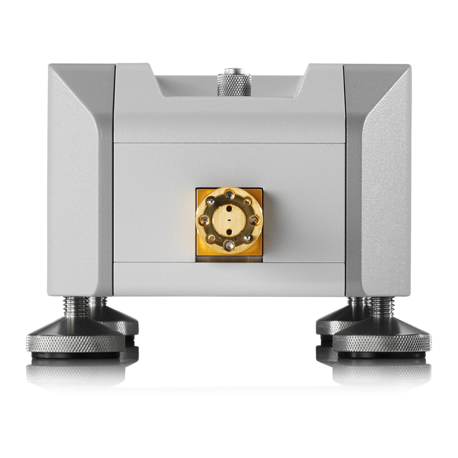
® Instrument tour R&S ZCxxx Test port adapter (waveguide flange) Instrument tour This chapter gives an overview of the controls and connectors of the frequency converter. Test port adapter (waveguide flange) The test port with a mounted test port adapter is located at the front of the instru- ment. - Page 14 ® Instrument tour R&S ZCxxx Test port adapter (waveguide flange) Figure 4-2: Test port adapter of R&S ZC330 Risk of damaging waveguide flanges The waveguide flanges of the converter and of the test port adapters must be protected against scratches and other mechanical damages. Further- more the waveguides must be shielded from dust.
-
Page 15: Output Power-Adjusting Knob
® Instrument tour R&S ZCxxx Output power-adjusting knob Figure 4-3: Angled hex ball driver R&S ZCAW (accessory) For precision calibrations and measurements, use the inner dowels at the test port adapter. A tight and accurate connection is important to ensure precise mea- surement results. -
Page 16: Rear Panel
® Instrument tour R&S ZCxxx Rear panel verter is mounted upside down, e.g. on a wafer prober. If you turn the knob, a receiver power calibration remains valid, while a system error calibration has to be repeated if it refers to more than one port. To set a flat output power over frequency just by entering a dBm value in the VNA firmware, the leveling functionality of option R&S ZNA-K8 can be used. - Page 17 ® Instrument tour R&S ZCxxx Rear panel Figure 4-4: Rear view of the frequency converter 4.3.1 Power supply connector and status LED To supply the R&S ZCxxx with power, connect it to the external DC power supply R&S ZCPS. Always switch the power supply off before removing the DC cable.
- Page 18 ® Instrument tour R&S ZCxxx Rear panel If an error occurs, a warning message on the VNA indicates the current error condition (fan, voltage, temperature). Warning message and converter LED remain in the respective state as long as the error condition persists. If more than one error condition applies, warning message and LED show the most severe one.
- Page 19 ® Instrument tour R&S ZCxxx Rear panel Connecting the control cable Connect the control connector to one of the EXTATT CTRL front panel connec- tors of an R&S ZVA equipped with option R&S ZVA-B8. The required cable is supplied with the converter. The numbers below the EXTATT CTRL connectors denote the controlled analyzer ports.
-
Page 20: Rf Connections
® RF connections R&S ZCxxx RF connections The R&S ZNA offers various possibilities to connect and operate one or more fre- quency converters R&S ZCxxx. In the following descriptions, we focus on the standard setups for 2 and 4 con- verters, which use the following hardware options: ●... - Page 21 ® RF connections R&S ZCxxx R&S ZNA-B8 (rear panel LO output) R&S ZV-Z195 Var. 37 R&S ZNA-B26 (Direct IF I/O) R&S ZNA-K8 Port adapters required for R&S ZNA50/67 (included in R&S ZCAKN) Splitter 1-to-4 (included in R&S ZCAKN) LO from Port adapters R&S ZNA-B8 (included in R&S ZCAKN)
-
Page 22: Connection Procedure
® RF connections R&S ZCxxx Connection procedure Therefore always use an appropriate torque wrench, suitable for the type of con- nector. Rohde & Schwarz offers an optional 5/16” torque wrench that fits for SMA, 3.5 mm, 2.92 mm and 1.85 mm connectors (R&S ZN-ZTW variant 35). Similar wrenches are available for other sizes of spanner, too. -
Page 23: Input Connectors (Rf In, Lo In)
® RF connections R&S ZCxxx Input connectors (RF IN, LO IN) ● Once the R&S ZNA firmware has registered a converter, the USB con- nection is no longer required. ● Repeat step 4 whenever you are not sure whether a suitable converter configuration is already active. -
Page 24: Output Connectors (Meas Out, Ref Out)
® RF connections R&S ZCxxx Adaption kits R&S ZCAKN Output connectors (MEAS OUT, REF OUT) For the R&S ZNA standard setup, proceed as follows: 1. Connect the MEAS OUT connectors of the converters to the IF Meas connec- tors of the R&S ZNA. 2. - Page 25 ® RF connections R&S ZCxxx Adaption kits R&S ZCAKN – R&S ZV-Z193: Test port cable 0 Hz to 26.5 GHz, 3.5 mm (f) – 3.5 mm (m) Available in different lengths. ● Splitters – R&S ZN-Z1229: LO 1-to-2 power divider, 2.92 mm (f) connectors –...
-
Page 26: Basic Operation
® Basic operation R&S ZCxxx Required equipment Basic operation This chapter describes how to configure the standard setup with an R&S ZNA network analyzer and two frequency converters R&S ZC330, for 2-port transmis- sion measurements. Measurements using other converters of the R&S ZCxxx family are performed in an analogous way. -
Page 27: Configuration And Measurement Steps
® Basic operation R&S ZCxxx Configuring the converter setup Configuration and measurement steps Follow the connection sequence described in Chapter 5.1, "Connection pro- cedure", on page 22. Configuring the measurement setup and measuring the DUT involves the follow- ing steps: 1. - Page 28 ® Basic operation R&S ZCxxx Configuring the converter setup "Converter 1" is the converter connected to VNA port 1, "Converter 2" the con- verter connected to VNA port 2. 2. In the "Converter Configuration" dialog, verify that your R&S ZNA has regis- tered your converters.
- Page 29 ® Basic operation R&S ZCxxx Configuring the converter setup Figure 6-1: Standard setup with two converters 4. Select "OK" to apply the converter configuration and close the dialog. The R&S ZNA now adjusts the frequencies and source power levels. The fre- quencies correspond to the maximum frequency range of the configured con- verters, the source power levels also take the cable and splitter losses into account.
-
Page 30: Establishing The Rf Connections
® Basic operation R&S ZCxxx Scalar power calibration and leveling (optional) The resulting frequency and source power levels can be viewed – and tweaked – in the port settings dialog (Channel – [Channel Config] key > "Port Config" tab > "Port Settings ..."). For details, see the R&S ZNA help system or user manual. - Page 31 ® Basic operation R&S ZCxxx Scalar power calibration and leveling (optional) Perform a source flatness calibration, if the default values for cable and split- ter losses deviate significantly from the actual ones (sum deviation > 2 dB). step 5 Chapter 6.3, "Configuring the converter setup", on page 27.
- Page 32 ® Basic operation R&S ZCxxx Scalar power calibration and leveling (optional) b) "Meas. Receiver" A measurement receiver calibration adjusts the power readings at the receive port, by default based on an existing reference receiver calibration. With an existing reference receiver calibration for port 1, to calibrate the measurement receiver of port 1, connect a Short to the waveguide port of converter 1 and select port 1 as source.
- Page 33 ® Basic operation R&S ZCxxx Scalar power calibration and leveling (optional) c) "Leveling Table (Global)" Perform leveling if you want the power levels at the waveguide port to be constant over frequency. Also perform leveling if you want to have fre- quency-independent, variable, known power levels at the waveguide port.
-
Page 34: System Error Correction
® Basic operation R&S ZCxxx Measurement System error correction For precise S-parameter measurements, a system error correction is recommen- ded. System error correction requires a calibration kit for the waveguide band of the specific R&S ZCxxx converter. The (universal data of the) R&S ZVA-WRxx kits are pre-installed in the R&S ZNA firmware. -
Page 35: Additional Information
® Basic operation R&S ZCxxx Additional information ● After power-up, a warm-up time of one hour is required to ensure accu- rate measurements. ● Measurement results can be degraded if the setup is exposed to an electromagnetic field at the IF frequency (default: 279 MHz). ●... -
Page 36: Maintenance And Disposal
® Maintenance and disposal R&S ZCxxx Disposal Maintenance and disposal The product does not require regular maintenance. It only requires occasional cleaning. It is however advisable to check the nominal data from time to time. Cleaning Cleaning the product Use a dry, lint-free cloth to clean the product. When cleaning, keep in mind that the casing is not waterproof. -
Page 37: Contacting Customer Support
® Contacting customer support R&S ZCxxx Contacting customer support Technical support – where and when you need it For quick, expert help with any Rohde & Schwarz product, contact our customer support center. A team of highly qualified engineers provides support and works with you to find a solution to your query on any aspect of the operation, program- ming or applications of Rohde &... -
Page 38: Annex
® Setup and operation with R&S ZVA/ZVT R&S ZCxxx Connecting the RF cables Annex Setup and operation with R&S ZVA/ZVT Connecting the RF cables The connectors RF IN, LO IN, MEAS OUT and REF OUT have to be connected to the VNA; LO IN can alternatively be connected to an external generator. Switch off the converter power supply R&S ZCPS before connecting the RF cables. - Page 39 ® Setup and operation with R&S ZVA/ZVT R&S ZCxxx Connecting the RF cables Connection Procedure 1. Connect the frequency converter to the power supply R&S ZCPS and power up R&S ZVA/ZVT and R&S ZCPS. 2. Establish a USB connection between frequency converter and VNA 3.
- Page 40 ® Setup and operation with R&S ZVA/ZVT R&S ZCxxx Connecting the RF cables an external generator is used, a power splitter is required for a two-port con- verter setup. If the outputs of the splitter are so close that two cables cannot be mounted in parallel, additional angled adapters are required.
- Page 41 ® Setup and operation with R&S ZVA/ZVT R&S ZCxxx Connecting the RF cables R&S ZVA50 and R&S ZVA67 require additional 1.85 mm to 2.92 mm adapters to connect the cables. These adapters are offered as complementary adaption kits (see Chapter A.1.4, "Adaption Kits R&S ZCAK", on page 41).
-
Page 42: Basic Operation
® Setup and operation with R&S ZVA/ZVT R&S ZCxxx Basic Operation It includes a power splitter and two right angled SMA (m-m) adapters. ● For the R&S ZVA50, Rohde & Schwarz offers the adaption kit R&S ZCAK Var. 50 (order number 1323.7746.50). It includes four 1.85 mm (f) to 2.92 mm (m) adapters and four 1.85 mm (m) to 2.92 mm (f) adapters. - Page 43 ® Setup and operation with R&S ZVA/ZVT R&S ZCxxx Basic Operation ● Option R&S ZVAxx-B16/R&S ZVT20-B16, "Direct Generator/Receiver Access" at each port ● Option R&S ZVA-K8, "Converter Control" ● Calibration kit for the respective WM-xxxx waveguide Special requirements for particular converter models ●...
- Page 44 ® Setup and operation with R&S ZVA/ZVT R&S ZCxxx Basic Operation A.2.3 Activating the frequency converter mode To activate the converter mode for a setup without external generator, establish a USB connection between converter and VNA. Wait for the dialog box to appear and confirm the prompt "Configure Two-Port Measurement Setup…?".
- Page 45 ® Setup and operation with R&S ZVA/ZVT R&S ZCxxx Basic Operation Figure A-3: Frequency Converter tab in System Configuration dialog A.2.4 Connecting the frequency converters Each frequency converter must be connected to power supply, analyzer and DUT. Please refer to the following sections for details. ●...
- Page 46 ® Setup and operation with R&S ZVA/ZVT R&S ZCxxx Basic Operation the corresponding a-wave. See section "Power Calibration for Converters without Electronic Attenuators" in the R&S ZVA/ZVT online help for details. Accepting some limitations w.r.t. temperature stability, the R&S ZVA Frequency Converter Leveling Tool can be applied for the linearization of output power in the frequency range of interest.
- Page 47 ® Setup and operation with R&S ZVA/ZVT R&S ZCxxx Basic Operation Please note that measurement results can be degraded if the setup is exposed to an electromagnetic field at the R&S ZVA/ZVT receiver frequency (typically 279 MHz). A.2.7 Additional information For a comprehensive description of the frequency converter mode, including remote control, refer to the R&S ZVA/ZVT online help system or to the printable operating manual, which is available for download from the Rohde &...
-
Page 48: Index
® Index R&S ZCxxx Index REF OUT ..........18 Required Equipment ......26, 42 Adjusting knob ......... 15 RF connection ........20, 38 Attenuator control connector (R&S ZC90E RF connector inputs ........ 18 only) ............18 RF connector outputs ......18 RF IN ............18 Basic operation ........26, 42 Safety instructions Warning messages .......
Need help?
Do you have a question about the ZC Series and is the answer not in the manual?
Questions and answers