Table of Contents
Advertisement
Quick Links
Advertisement
Table of Contents

Related Manuals for R&S ZC Series


Summary of Contents for R&S ZC Series
- Page 1 ® R&S ZCxxx Converters Getting Started (;ÛÁÆ2) 1177.5156.02 ─ 03...
- Page 2 ® This manual describes the Rohde & Schwarz models of the R&S ZCxxx family of frequency converters, where xxx denotes the converter's upper frequency limit. ® Throughout this manual, the converter R&S ZC330 is used as a representation ® for converters of the R&S ZCxxx family.
-
Page 3: Table Of Contents
® Contents R&S ZCxxx Contents 1 Safety Instructions..............5 2 Preparing for Use..............7 2.1 Test Port Adapter (Waveguide Flange)..........7 2.2 Output Power Adjusting Knob.............8 2.3 Rear Panel..................... 9 2.4 Putting the Converter into Operation..........11 2.5 Maintenance..................19 2.6 Storage and Transport............... 20 3 Basic Operation.............. - Page 4 ® Contents R&S ZCxxx Getting Started 1177.5156.02 ─ 03...
-
Page 5: Safety Instructions
® Safety Instructions R&S ZCxxx Safety Instructions The frequency converters R&S ZCxxx (xxx indicating the upper frequency limit in GHz) have been designed and tested in accordance with the EC Certificate of Conformity and each of them has left the manufacturer’s plant in a condition fully complying with safety standards. - Page 6 ® Safety Instructions R&S ZCxxx 3. At the analyzer GUI, when prompted to configure a two-port measurement setup, select "Yes" Now the RF and LO cables can be connected safely. You have to repeat this procedure whenever you are not sure if the fre- quency converter mode for your particular R&S ZCxxx model is already active.
-
Page 7: Preparing For Use
® Preparing for Use R&S ZCxxx Test Port Adapter (Waveguide Flange) Preparing for Use This chapter gives an overview of the controls and connectors of the frequency converter and provides all information that is required to put the converter into operation and connect external devices. -
Page 8: Output Power Adjusting Knob
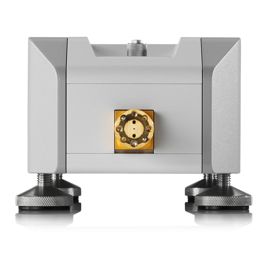
® Preparing for Use R&S ZCxxx Output Power Adjusting Knob the flange of the DUT also has holes for them and the accuracy of the connection shall be enhanced. Fig. 2-2: Test port adapter of R&S ZC330 Risk of damaging waveguide flanges The waveguide flanges of the converter and of the test port adapters must be protected against scratches and other mechanical damages. -
Page 9: Rear Panel
® Preparing for Use R&S ZCxxx Rear Panel is turned after power calibration, the power calibration remains valid but system error calibration has to be repeated if it refers to more than one port. In order to set a flat output power over frequency just by entering a dBm value in the NWA firmware, the Frequency Converter Leveling Tool can be used. - Page 10 ® Preparing for Use R&S ZCxxx Rear Panel 2.3.1 Power Supply Connector In order to supply the R&S ZCxxx with power, connect it to the external DC power supply R&S ZCPS. Always switch the power supply off before removing the DC cable. For details, see the User Manual of the R&S ZCPS.
-
Page 11: Putting The Converter Into Operation
® Preparing for Use R&S ZCxxx Putting the Converter into Operation 2.3.3 RF Connectors – Output Two SMA female output connectors: MEAS OUT (measurement signal output) and REF OUT (reference signal output). For correct cabling please refer to chapter 2.4.8, "Connecting the Cables", on page 15. - Page 12 ® Preparing for Use R&S ZCxxx Putting the Converter into Operation ● converter ● DC supply cable ● USB cable ● IF cable EXT REF ● IF cable EXT MEAS ● plastic case with 8 flange screws 4-40 UNC 7.6 and 4 flange screws 4-40 UNC 9.24 ●...
- Page 13 ® Preparing for Use R&S ZCxxx Putting the Converter into Operation ● All ventilation openings must be unobstructed. Risk of instrument and DUT damage To avoid damage of electronic components of the DUT and the frequency converter, the operating site must be protected against electrostatic dis- charge (ESD).
- Page 14 ® Preparing for Use R&S ZCxxx Putting the Converter into Operation Firmware and Operating System Requirements Support of the R&S ZCxxx converters requires firmware version 3.40 or higher to be installed on the NWA. If the operating system of the NWA is Windows®...
- Page 15 ® Preparing for Use R&S ZCxxx Putting the Converter into Operation than one fault condition is fulfilled, both warning message and LED show the most severe one. 2.4.8 Connecting the RF Cables The connectors RF IN, LO IN, MEAS OUT and REF OUT have to be connected to the NWA;...
- Page 16 ® Preparing for Use R&S ZCxxx Putting the Converter into Operation 1. Connect port 1 or port 2 of the analyzer to RF IN of the converter. 2. Connect port 3 or port 4 of the analyzer to LO IN of the converter. For NWAs with 4 sources (R&S ZVA24 var.
- Page 17 ® Preparing for Use R&S ZCxxx Putting the Converter into Operation Connecting the output connectors (MEAS OUT, REF OUT) Suitable cables for connecting the output connectors to the network analyzer are included in the converter shipment. The connectors of these cables are labeled accordingly.
- Page 18 ® Preparing for Use R&S ZCxxx Putting the Converter into Operation cables. Rohde & Schwarz offers three different adaption kits R&S ZCAK to meet the requirements of different NWAs: ● For the R&S ZVA24 var. 28 and the R&S ZVA40 var. 48 (NWAs with four sources), Rohde &...
-
Page 19: Maintenance
® Preparing for Use R&S ZCxxx Maintenance Fig. 2-6: Angled hex ball driver R&S ZCAW (accessory) For precision calibrations and measurements, use the inner dowels at the test port adapter. A tight and accurate connection is very important to ensure precise measurement results. -
Page 20: Storage And Transport
® Preparing for Use R&S ZCxxx Storage and Transport For Rohde & Schwarz support center address and a list of useful R&S contact addresses refer to the pages at the beginning of this document. Storage and Transport For storage and transport, use either the original packaging or the transport case R&S ZCSTC, order number 1323.7730.00 (see figure 2-7). -
Page 21: Basic Operation
® Basic Operation R&S ZCxxx Required Equipment Basic Operation This chapter describes the use of an R&S ZVA vector network analyzer and two frequency converters R&S ZCxxx for 2-port transmission measurements. Measurements using other converters of the R&S ZCxxx family are performed in an analogous way. -
Page 22: Measurement Principle
® Basic Operation R&S ZCxxx Measurement Principle Firmware and Operating System Requirements Support of the R&S ZCxxx converters requires firmware version 3.40 or higher to be installed on the NWA. If the operating system of the NWA is Windows® XP, make sure that it has been upgraded at least up to service pack 2. -
Page 23: Activating The Frequency Converter Mode
® Basic Operation R&S ZCxxx Activating the Frequency Converter Mode Activating the Frequency Converter Mode To activate the converter mode for a setup without external generator, establish a USB connection between converter and NWA. Wait for the dialog box to appear and confirm the prompt "Configure Two-Port Measurement Setup…?". -
Page 24: Connecting The Frequency Converters
® Basic Operation R&S ZCxxx Connecting the Frequency Converters Fig. 3-1: Frequency Converter tab in System Configuration dialog Connecting the Frequency Converters Each frequency converter must be connected to power supply, analyzer and DUT. Please refer to the following sections for details. ●... -
Page 25: Measurement
® Basic Operation R&S ZCxxx Measurement performed. With the help of a receiver power calibration, however, precise moni- toring of the output power of converter port i is possible by measuring the corre- sponding a wave. See section "Power Calibration for Converters without Elec- tronic Attenuators"... -
Page 26: Additional Information
® Basic Operation R&S ZCxxx Additional Information Additional Information For a comprehensive description of the frequency converter mode, including remote control, refer to the R&S ZVA/ZVT online help system or to the printable operating manual, which is available for download from the Rohde & Schwarz web site (www.rohde-schwarz.com). -
Page 27: Index
® Index R&S ZCxxx Index Adjusting knob ........... 8 Storing the instrument ......20 System Configuration ......24 System error correction ......25 Basic operation ........21 Test port ............ 7 Test port adapter ........7 Calibration ..........24 Transporting the instrument ....20 Converter setup ........
Need help?
Do you have a question about the ZC Series and is the answer not in the manual?
Questions and answers