
Related Manuals for thermital AF ACS


Summary of Contents for thermital AF ACS
- Page 1 ISTRUZIONI D’USO E D’INSTALLAZIONE OPERATING AND INSTALLATION INSTRUCTIONS AF ACS EMIX...
-
Page 2: Table Of Contents
Installare AF ACS Collegamenti elettrici Pannello di controllo Come utilizzare AF ACS Come utilizzare e configurare le resistenze elettriche Scollegare e disinstallare AF ACS Collegare AF ACS ad un impianto solare termico Gamma e confomità MODELLO CODICE AF ACS 20112950 DICHIARAZIONE DI CONFORMITÀ... - Page 3 IMPORTANTE! Leggere prima di iniziare l’installazione Questo sistema deve seguire rigidi standard di sicurezza e di funzionamento. Per l’installatore o il personale di assistenza è molto importante installare o riparare il sistema di modo che quest’ultimo operi con sicurezza ed efficienza. Per un’installazione sicura e un buon funzionamento è...
- Page 4 Luogo d’installazione Si raccomanda di far installare questo apparecchio da un tecnico qualificato seguendo le istruzioni di installazione allegate. AVVERTIMENTO Non installare questo apparecchio dove ci sono fumi, gas infiammabili o molta umidità, come in una serra. Non installare l’unità dove ci sono apparecchiature che generano un calore eccessivo. Non installare l’unità...
-
Page 5: Introduzione
Introduzione AF ACS è l’innovativa unità interna in grado di fornire acqua calda ad uso sanitario da fonte termodinamica, in tutte le stagioni dell’anno, cioè indipendentemente dal modo di funzionamento del sistema di climatizzazione/riscaldamento. AF ACS è un componente che si aggiunge alla gamma già molto ampia di unità interne. - Page 6 Lo schema seguente illustra il concetto esposto sopra ed evidenzia una configurazione di sistema in cui coesistono tre unità interne ad espansione diretta, un hydrokit per un impianto a pavimento ed un AF ACS, tutti collegati ad una AFEX 110.
-
Page 7: Dati Di Targa
272x527x285 Viene fornito in dotazione un filtro raccogli impurità da ¾” da inserire a monte di AF ACS se non già presente nell’im- pianto. E’ caldamente consigliato un addolcitore per acqua o un filtro ai polifosfati per evitare il deposito di calcare e la conseguente riduzione di prestazione dello scambiatore. - Page 8 AF ACS, lasciando sfiatare dal lato dell’ac- qua fredda 3 (si consiglia di inserire una valvola di sfiato). AF ACS viene fornito con un filtro dell’acqua (il filtro è fissato con una fascetta all’interno dell’unità AF ACS) da porre in serie all’ingresso dell’acqua fredda a monte di AF ACS con senso di circolazione verso AF ACS (vedi freccia sul filtro).
- Page 9 Limiti di collegamento Circuito frigorifero AF ACS è un componente che si può collegare contemporaneamente alle altre tipologie di unità interna senza specifi- che limitazioni, sfruttando l’apposita connessione frigorifera per AF ACS e tenendo in debito conto la lunghezza delle tubazioni di AF ACS da sommare alla lunghezza totale prevista dall’unità...
- Page 10 AF ACS è progettato per operare con pressioni dell’acqua fino a 10 bar e così è compatibile con le reti di distribuzione dell’acqua di tutte le nazioni Europee; esso rispetta le più stringenti norme Europee per il doppio isolamento tra la cir-...
-
Page 11: Collegamenti Elettrici
NOTA 1: pur consumando solo un massimo di 70 W, AF ACS deve sempre essere alimentato separatamente (fase, neutro e terra) dall’unità esterna per supportare il carico di eventuali resistenze elettriche del serbatoio o scalda acqua elettrico. -
Page 12: Pannello Di Controllo
Collegamenti elettrici • Unità esterne AFEX 050 - AFEX 065 collegare il cavo bus di AF ACS in parallelo ai morsetti C1 C2 sull’unità esterna. Non ci sono morsetti dedicati per il collegamento del cavo bus per l’unità AF ACS. -
Page 13: Come Utilizzare E Configurare Le Resistenze Elettriche
Il led blu acceso segnala che una resistenza elettrica è in funzione. AF ACS è in grado di gestire direttamente fino a tre resistenze elettriche da 1.5 kW ciascuna, ognuna delle quali colle- gata al proprio e specifico morsetto. - Page 14 Gli utenti finali possono spegnere l’unità AF ACS se non desiderano usufruire di questa funzione. Collegamento AF ACS - Solo applicazioni ACS AF ACS può essere utilizzato con le unità esterne I-Series in una specifica configurazione allo scopo di creare un siste- ma a pompa di calore solo per la produzione di ACS.
-
Page 15: Scollegare E Disinstallare Af Acs
Scollegare e disinstallare AF ACS Nel caso in cui AF ACS sia collegato ad una normale porta per unità interne la disinstallazione di AF ACS comporta le stesse procedure che si attuano quando si scollega un’unità interna qualsiasi. Nel caso in cui AF ACS sia collegato alla relativa PORTA EMX e per qualsiasi ragione debba essere sostituito, è neces- sario eseguire la disinstallazione con l’ausilio di un recuperatore di gas:... -
Page 23: General Information
Control panel How to use AF ACS How to use and set the electrical heater elements How to disconnect and/or remove AF ACS unit How to connect AF ACS to a solar thermal system Range and confomity MODEL CODE AF ACS... - Page 24 IMPORTANT! Please read before installation This system meets strict safety and operating standards. For the installer or service person, it is important to install or service the system so that it operates safely and efficiently. For safe installation and trouble-free operation, you must: •...
- Page 25 Installation location We recommend this appliance to be installed properly by qualified installation technicians in accordance with the installation instructions provided with the unit. WARNING Do not install this appliance where there are fumes or flammable gases, or in an extremely humid space such as a green house.
-
Page 26: Introduction
AF ACS is designed to provide hot water up to thermodynamic 80°C when the heat pump is in both heating and cooling mode, without priority cycles or temporary interruption of the cooling service. - Page 27 The following diagram illustrates the concept exposed on the previous page and shows a system configuration where three indoor direct expansion units, a hydrokit for a floor system and an AF ACS coexist, all connected to an AFEX 110 AFIP...
-
Page 28: Rating Data
268x527x285 mm A 3/4” water filter is supplied with AF ACS to be installed upstream of tap water connection. It is warmly suggested to install a softener or a polyphosphate filter to avoid limestone and consequently performance drop; in addition to this, service valves, mixing valve and vent valve are suggested. - Page 29 3 and hot water tap in parallel of the water port number 4. Before closing the hydraulic circuit eliminate the air inside the AF ACS unit, purging it from the cold water side 3 (a vent valve is recommended).
- Page 30 AF ACS and duly considering the length of the AF ACS pipe to be added to the total length set by the outdoor unit (we advise a specific insulation of the AF ACS pipes to guarantee the minimum dispersion of energy).
- Page 31 080 limits in quadri application is 65 meters, with additional load. You have to add: 15 g/m x 17 m. Water circuit AF ACS is able to manage any third party tank, including electric boilers; this unique feature makes AF ACS an excel- lent solution not just for new systems but also to protect existing investments.
-
Page 32: Electrical Connections
Note: AF ACS electrical consumption is very low but in case electrical heater elements are connected, AF ACS has to support the flow of big amount of electrical energy; for that reason it is necessary to power AF ACS independently to the power supplied by the outdoor unit. -
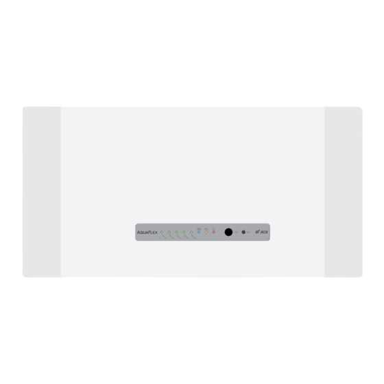
Page 33: Control Panel
• AF ACS is designed to be always ON; in case you want to switch it OFF you have to press for 4” the push button exactly as you want to switch on, then when the green LED will be switched off and the red LED will be switched ON you have to release immediately the push button, otherwise the unit will go into the electrical heater configura- tion (the blue led will pass from off to on). -
Page 34: How To Use And Set The Electrical Heater Elements
50ºC. Anti legionella cycle is a special operation function performed by AF ACS. The goal of this function is to heat all water buffer volume. In this way, all bacteria that may have been inside the buffer would be killed. - Page 35 10’, all the connected electrical heaters will switch on up to the reaching of the setpoint. End users can switch off AF ACS if they do not want to have this option.
-
Page 36: How To Disconnect And/Or Remove Af Acs Unit
In case of forced circulation solar system, by the water point of view, AF ACS must be connected to the solar tank exactly like any other tank in parallel to the cold and hot tap water (mixing valve); by the electric point of view AF ACS could be submitted to the solar control box if it has a dry contact to enable/disable AF ACS energy support to the water. - Page 44 Via Mussa, 20 Z.I. - 35017 Piombino Dese (PD) - Italia Tel. 049.9323911 - Fax 049.9323972 - www.thermital.it - email: info@thermital.it Poichè l’Azienda è costantemente impegnata nel continuo perfezionamento di tutta la sua produzione, le caratteristiche estetiche e dimensionali, i dati tecnici, gli equipaggiamenti e gli accessori, possono essere soggetti a variazione.
Need help?
Do you have a question about the AF ACS and is the answer not in the manual?
Questions and answers