Table of Contents
Advertisement
Quick Links
This publication describes the installation procedure for the 4100U and 4100ES Flex Amplifiers.
Introduction
This product is compatible with both 4100U and 4100ES Fire Alarm Control Panels (FACP).
IMPORTANT: Verify FACP System Programmer, Executive, and Slave Software
In this Publication
This publication discusses the following topics:
©
2003, 2009, 2011 SimplexGrinnell LP. All rights reserved
Specifications and other information shown were current as of publication and are subject to change without notice.
Simplex and the Simplex logo are trademarks of Tyco International Ltd. and its affiliates and are used under license.
compatibility when installing, or replacing system components. Refer to
the Technical Support Information and Downloads website for
compatibility information.
Cautions, Warnings, and Regulatory Information
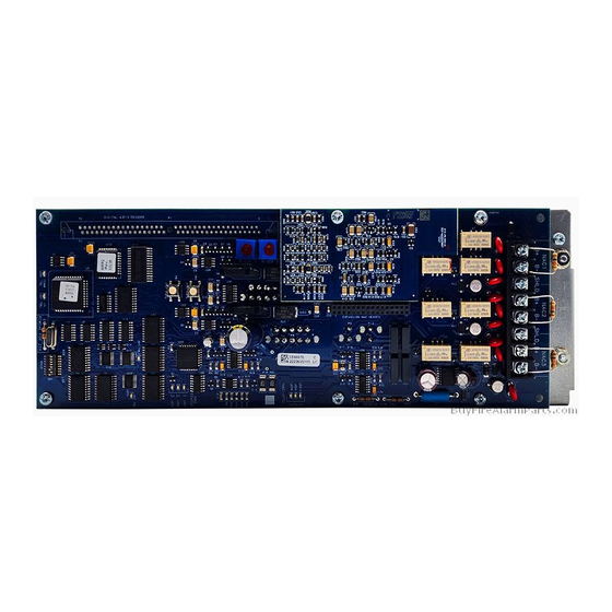
Introduction to the Flex Amplifiers
Amplifier Specifications
Setting the Baud Rate and Address
Installing the Amplifier onto the PDI
Amplifier Field Wiring
LED Indications
Troubleshooting
firealarmresources.com
Installation Instructions
Topic
Flex Amplifiers
See Page
2
3
5
6
8
11
15
16
579-173
Rev. H
Advertisement
Table of Contents


Need help?
Do you have a question about the Flex 4100U and is the answer not in the manual?
Questions and answers