
Related Manuals for Rise MAX.CP

Summary of Contents for Rise MAX.CP
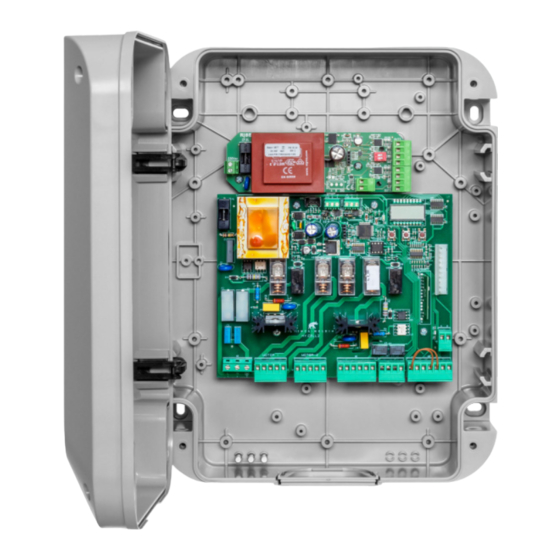
- Page 1 ITA/GB 05/2021 rev 0 MAX.CP Made in Italy Manuale di installazione Centrale di comando per 1 o 2 dissusasori Installation manual 1 or 2 bollards control unit...
- Page 3 SERIAL 1 SERIAL 0 GND B A GND B A MAX.CP T100mA 31 32 F10A F10A SHIELD BLINK/ BLINK/ AUX1 AUX2 24Vac LSC1LSO1 COM OP CL PHO STP LSC2LSO2 EFO E.V. EFO E.V. 24 25 26 27 28 29 30...
-
Page 4: Emergency Push Button
MAX.CP BLINK/ BLINK/ AUX1 AUX2 24Vac LSC1LSO1 COM OP CL PHO STP LSC2LSO2 EFO E.V. EFO E.V. 24 25 26 27 28 29 30 12 13 MAX M30 (1) E.V. MAX M30 (2) E.V. MAX.CP AUX1 AUX2 24Vac LSC1LSO1 COM OP CL PHO STP LSC2LSO2 EV.EFO... - Page 5 CP.BL (optional) CP.BL (optional) AUT2 LED2 BUZ2 230Vac DIP-SWITCH LED1 BUZ1 AUT1 MAX.CP AUX1 = 5 AUX1 AUX2 24Vac LSC1LSO1 COM OP CL PHO STP LSC2LSO2 EV.EFO EV.EFO 24 25 26 27 28 29 30 12 13 MAX M30 (1) E.V.
-
Page 6: Informazioni Generali
AVVERTENZE INFORMAZIONI GENERALI E’ vietato l’utilizzo del prodotto per scopi o con modalità non previste nel presente manuale. Usi non corretti possono essere causa di danni al prodotto e mettere in pericolo persone e cose. Si declina ogni responsabilità dall’inosservanza della buona tecnica nella co- struzione dei cancelli, nonché... - Page 7 CENTRALE DI COMANDO MAX.CP FUNZIONI INGRESSI/USCITE (FIG.6) Morsetti Funzione Descrizione Ingresso 230Vac 50/60Hz 1/2/3 Alimentazione 1: L-Fase - 2: N-Neutro - 3: GND-Terra Collegamento dissuasore 1: 4/5/6 Motore 1 4: Discesa - 5: COM - 6: Salita Uscita per dispositivo lampeggiante o EFO, configurabile con logica EFO.
- Page 8 PARAMETRI, LOGICHE E FUNZIONI SPECIALI Nelle tabelle di seguito vengono descritte le singole funzioni disponibli nella centrale. PARAMETRI (PAR) MIN-MAX- MENU FUNZIONE MEMO (Default) Tempo di salita automatica del dissuasore 1 e del dissuasore 2. 3-240-(10s) Al termine del tempo impostato la centrale comanda la risalita del dissuasore. Tempo lavoro dissuasore 1.
- Page 9 Abilita o disabilita il funzionamento simultaneo dei dissuasori. On: l’ingresso DOWN si comporta come un ingresso PP per il dissuasore 1, l’ingresso UP si comporta come ingresso PP per il dissuasore 2 (OFF) Off: l’ingresso DOWN aziona entrambi i dissuasori in discesa, l’ingresso UP aziona entrambi i dissuasori in salita.
- Page 10 Fissare la scheda nelle apposite sedi utilizzando le viti V1 e V2 (Fig. 10). Procedere al collegamento alla centrale MAX.CP e al dissuassore M30 come indicato nello schema. La scheda dispone di due dip-switch per impostare la modalita di funzionamento quando il dissuasore è completamente alzato:...
- Page 11 DIAGNOSTICA Durante il normale funzionamento, il display LCD visualizza lo stato degli ingressi e delle LSO1 LSC1 LSO2 LSC2 uscite come da schema a fianco. Ad ogni attivazione di un ingresso/uscita corrisponde DOWN UP l’accensione del relativo segmento del display LCD. La modalità...
-
Page 12: Technical Data
WARNING The product shall not be used for purposes or in ways other than those for which the product is intended for and as described in this manual. Incorrect uses can damage the product and cause injuries and damages. The company shall not be deemed responsible for the non-compliance with a good manufacture technique of gates as well as for any deformation, which might occur during use. - Page 13 MAX.CP CONTROL UNIT INPUT/OUTPUT FUNCTIONS (FIG.6) Terminals Department Description 1/2/3 Input 230Vac 50/60Hz Supply 1: L-phase - 2: N-Neutral - 3: GND-Ground 4/5/6 Bollard connection 1: Motor 1 4: Descent - 5: COM - 6: Ascent Output for flashing or EFO device, configurable with EFO logic.
- Page 14 PARAMETERS, LOGICS AND SPECIAL FUNCTIONS The following tables describe the individual functions available in the control unit. PARAMETERS (PAR) MENU FUNCTION MEMO MIN-MAX-(Default) Automatic ascent time of bollard 1 and bollard 2. 3-240-(10s) At the end of the set time the control unit commands the bollard ascent again. Bollard working time 1.
- Page 15 Enables or disables pre-flashing. (OFF) On: Pre-flashing enabled. The flashing output (7/8 and 12/13) is activated 3 seconds PREl before the motor starts (do not use with EFO device installed). Off: Pre-flashing disabled. Enables/disables timed operation of bollards. (OFF) ON: Timed operation of the bollards (the operating time is defined by parameters TM1 nlsu and TM2).
- Page 16 Fix the board in place using screws V1 and V2 (Fig. 10). Proceed to connect the MAX.CP control unit and the M30 bollard as shown in the diagram. The board has two dip-switches to set the operating mode when the bollard is fully raised:...
- Page 17 Dichiarazione di Conformità UE (DoC) Nome del produttore: Rise S.r.l Indirizzo: Via della Tecnica, 10 - 36010 Velo d'Astico (VI) - Italia Telefono: +39 0444 751401 Indirizzo e-mail: info@riseweb.it Dichiara che il documento è rilasciato sotto la propria responsabilità e appartiene al seguente prodotto: Tipo di prodotto: Centrale di comando 230Vac Modello/Tipo: MAX.CP...
- Page 18 EU Declaration of Conformity (DOC) Manufacturer’s name: Rise S.r.l Postal Address: Via della Tecnica, 10 - 36010 Velo d’Astico (VI) - Italia Telephone number:: +39 0444 751401 E-mail address info@riseweb.it Declare that the DOC is issued under our sole responsibility and belongs to the following product: Model/Product: 230Vac Control Unit Type: MAX.CP...
Need help?
Do you have a question about the MAX.CP and is the answer not in the manual?
Questions and answers