Advertisement
Quick Links
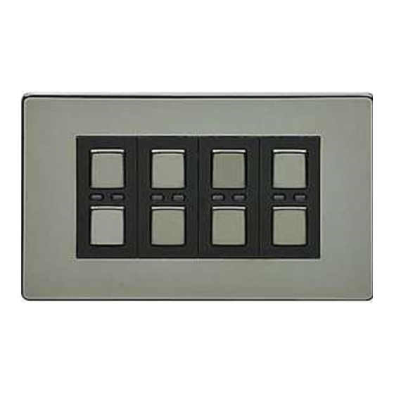
LightwaveRF
connect
4 Gang 2 Way RF Dimmer
Operation Manual
Model No: JSJS LW240
It is important to install this product in accordance
with the tting instructions below. Failure to do so
may render your guarantee void.
IMPORTANT: PLEASE RETAIN THESE INSTRUCTIONS
FOR FUTURE REFERENCE AND FOR GUIDANCE ON
THE ASSOCIATION OF REMOTE HANDSETS. FOR
HELP AND SETUP GUIDANCE PLEASE VISIT
www.lightwaverf.com
OVERVIEW:
Amber LED 'OFF'
Blue LED 'ON'
Advertisement

Related Manuals for LightwaveRF connect JSJS LW240


Summary of Contents for LightwaveRF connect JSJS LW240
- Page 1 LightwaveRF connect 4 Gang 2 Way RF Dimmer Operation Manual Model No: JSJS LW240 It is important to install this product in accordance with the tting instructions below. Failure to do so may render your guarantee void. IMPORTANT: PLEASE RETAIN THESE INSTRUCTIONS FOR FUTURE REFERENCE AND FOR GUIDANCE ON THE ASSOCIATION OF REMOTE HANDSETS.
- Page 2 FITTING AND WIRING INSTRUCTIONS: Important Things to Consider Before you Begin 1). Before commencing work, ALWAYS isolate the mains power supply and remove the fuse in the fuse box or switch o the circuit breaker in the consumer unit. 2). If unit is to be used as a replacement for an existing product, remove existing unit from its location and disconnect the wiring.
- Page 3 • Dimmable (only) LED bulbs - NOTE: min 15w total load on circuit required for reliable LED operation! For guidance on compatible bulbs please visit www.lightwaverf.com. The 4 gang LightwaveRF Connect Dimmer is NOT compatible with: • Wirewound transformers (generally older style) • Electric Motors Installation Guide 1.
- Page 5 5. Strip the cable as shown then connect the wiring as per the diagrams below, ensure terminals are properly tightened and no bare wire is visible. NOTE: In order to have RF function, mains electricity must be connected to the Master (first) dimmer module.
- Page 6 7. Replace the plate – a ‘click’ sound should be heard to signify that the plate has been correctly replaced.
- Page 7 4 Gangs with 1-Way 4 Gangs with 2-Way...
- Page 8 ‘ON’ AND ‘OFF’ buttons until the blue and amber LEDs ash alternately. The dimmer switch is now in learning mode. 2. Using a LightwaveRF Connect Remote press the ‘ON’ button intended to be paired; the blue light on the dimmer switch will ash to con rm that the remote is now paired.
- Page 9 LEDs ash alternately. The dimmer switch is now in learning mode. 2. Using a LightwaveRF Connect Remote press the ‘OFF’ button intended to be un-paired; the amber light on the dimmer switch will ash to con rm that the remote is now unpaired.
-
Page 10: Operation
OPERATION: Switch ‘ON/OFF’ Manual ‘ON’ Button Press once to switch ‘ON’ (Blue LED indicator will illuminate). Manual ‘OFF’ Button Press once to switch ‘OFF’ (Amber LED indicator will illuminate). Manual Dimming using the Dimmer Switch Lowering Dim Level 1. Make sure the light is switched on. 2. - Page 11 If after setting a dim level the light is then switched o , the next time the light is switched on the light level will automatically return to the previous setting. Dimming control with a LightwaveRF Connect Remote Dimming down 1.
- Page 12 NOTE: If the RF range between the transmitter and receiver is too great to achieve reliable operation, the LightwaveRF SIGNAL BOOSTER may be used in conjunction with this product to increase the signal strength over greater distances. SPECIFICATION (per module): RF frequency: 433.92 MHz...
Need help?
Do you have a question about the connect JSJS LW240 and is the answer not in the manual?
Questions and answers