Table of Contents
Advertisement
Advertisement
Table of Contents
Troubleshooting

Related Manuals for Gigabyte GA-970A-UD3P


Summary of Contents for Gigabyte GA-970A-UD3P
- Page 1 GA-970A-UD3P User's Manual Rev. 2001 12ME-970AU3P-2001R...
- Page 3 No part of this manual may be reproduced, copied, translated, transmitted, or published in any form or by any means without GIGABYTE's prior written permission. In order to assist in the use of this product, GIGABYTE provides the following types of docu- mentations: For quick set-up of the product, read the Quick Installation Guide included with the product.
-
Page 4: Table Of Contents
Table of Contents Box Contents ........................6 Optional Items .........................6 GA-970A-UD3P Motherboard Layout ................7 GA-970A-UD3P Motherboard Block Diagram ..............8 Chapter 1 Hardware Installation ..................9 Installation Precautions ................... 9 ................... 10 Installing the CPU and CPU Cooler............... 12 1-3-1 Installing the CPU ....................12 1-3-2 Installing the CPU Cooler ..................14... - Page 5 Chapter 4 Drivers Installation ..................63 Installing Chipset Drivers ................63 Application Software ..................64 Technical Manuals ..................64 Contact......................65 System ......................65 Download Center ................... 66 Chapter 5 Unique Features...................67 BIOS Update Utilities ..................67 5-1-1 Updating the BIOS with the Q-Flash Utility ............67 5-1-2 Updating the BIOS with the @BIOS Utility ............70 EasyTune 6 ....................
-
Page 6: Box Contents
Box Contents GA-970A-UD3P motherboard Motherboard driver disk User's Manual Quick Installation Guide Four SATA cables I/O Shield The box contents above are for reference only and the actual items shall depend on the product package you obtain. The box contents are subject to change without notice. -
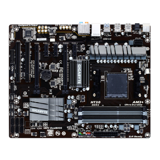
Page 7: Ga-970A-Ud3P Motherboard Layout
GA-970A-UD3P Motherboard Layout OPTICAL Socket AM3+ AUDIO AMD 970 Realtek ® GbE LAN GA-970A-UD3P ® CODEC AMD SB950 PCI1 SATA3 PCI2 COMA expansion card. For a longer expansion card, use other expansion slots. - 7 -... -
Page 8: Ga-970A-Ud3P Motherboard Block Diagram
GA-970A-UD3P Motherboard Block Diagram AM3+/AM3 CPU 1 PCI Express x16 Dual Channel Memory Hyper Transport PCIe CLK 4 USB 3.0/2.0 3 PCI Express x1 RJ45 ® Realtek ® GbE LAN PCIe CLK AMD 970 PCI Express Bus PCI Express Bus... -
Page 9: Chapter 1 Hardware Installation
Chapter 1 Hardware Installation Installation Precautions The motherboard contains numerous delicate electronic circuits and components which can become manual and follow these procedures: Prior to installation, make sure the chassis is suitable for the motherboard. warranty sticker provided by your dealer. These stickers are required for warranty validation. Always remove the AC power by unplugging the power cord from the power outlet before installing or removing the motherboard or other hardware components. - Page 10 AM3+ Socket: AMD AM3 Phenom ™ II processor/ AMD Athlon ™ II processor Hyper Transport 4800 MT/s North Bridge: AMD 970 Chipset South Bridge: AMD SB950 Memory 4 x DDR3 DIMM sockets supporting up to 32 GB of system memory the physical memory installed.
- Page 11 Internal 1 x front panel audio header Connectors 1 x S/PDIF Out header 1 x USB 3.0/2.0 header 3 x USB 2.0/1.1 headers 1 x serial port header 1 x Clear CMOS jumper Back Panel 1 x PS/2 keyboard/mouse port Connectors 1 x optical S/PDIF Out connector 8 x USB 2.0/1.1 ports...
-
Page 12: Installing The Cpu And Cpu Cooler
Installing the CPU and CPU Cooler Read the following guidelines before you begin to install the CPU: Make sure that the motherboard supports the CPU. Always turn off the computer and unplug the power cord from the power outlet before installing the CPU to prevent hardware damage. - Page 13 B. Follow the steps below to correctly install the CPU into the motherboard CPU socket. Before installing the CPU, make sure to turn off the computer and unplug the power cord from the power outlet to prevent damage to the CPU. CPU orientation if this occurs.
-
Page 14: Installing The Cpu Cooler
1-3-2 Installing the CPU Cooler Step 1: Step 2: Hook the CPU cooler clip to the mounting lug on Apply an even and thin layer of thermal grease on one side of the retention frame. On the other side, the surface of the installed CPU. push straight down on the CPU cooler clip to hook it to the mounting lug on the retention frame. -
Page 15: Installing The Memory
Installing the Memory Read the following guidelines before you begin to install the memory: Make sure that the motherboard supports the memory. It is recommended that memory of the same capacity, brand, speed, and chips be used. Always turn off the computer and unplug the power cord from the power outlet before installing the memory to prevent hardware damage. -
Page 16: Installing A Memory
1-4-2 Installing a Memory Before installing a memory module, make sure to turn off the computer and unplug the power cord from the power outlet to prevent damage to the memory module. DDR3 and DDR2 DIMMs are not compatible to each other or DDR DIMMs. Be sure to install DDR3 DIMMs on this motherboard. Notch DDR3 DIMM your memory modules in the memory sockets. -
Page 17: Installing An Expansion Card
Installing an Expansion Card Read the following guidelines before you begin to install an expansion card: Make sure the motherboard supports the expansion card. Carefully read the manual that came with your expansion card. Always turn off the computer and unplug the power cord from the power outlet before installing an expansion card to prevent hardware damage. -
Page 18: Back Panel Connectors
Back Panel Connectors USB 2.0/1.1 Port PS/2 Keyboard/Mouse Port Use this port to connect a PS/2 mouse or keyboard. Optical S/PDIF Out Connector This connector provides digital audio out to an external audio system that supports digital optical audio. Before using this feature, ensure that your audio system provides an optical digital audio in connector. USB 3.0/2.0 Port RJ-45 LAN Port The Gigabit Ethernet LAN port provides Internet connection at up to 1 Gbps data rate. -
Page 19: Internal Connectors
Mic In Jack (Pink) The Mic in jack. Microphones must be connected to this jack. be connected to the default Mic in jack. Refer to the instructions on setting up a 2/4/5.1/7.1-channel Internal Connectors ATX_12V F_PANEL F_AUDIO CPU_FAN SPDIF_O SYS_FAN1/SYS_FAN2 F_USB30 PWR_FAN F_USB1/F_USB2/F_USB3... - Page 20 1/2) ATX_12V/ATX (2x4 12V Power Connector and 2x12 Main Power Connector) off and all devices are properly installed. The power connector possesses a foolproof design. Connect the power supply cable to the power connector in the correct orientation. the computer will not start. To meet expansion requirements, it is recommended that a power supply that can withstand high required power, the result can lead to an unstable or unbootable system.
- Page 21 3/4/5) CPU_FAN/SYS_FAN1/SYS_FAN2/PWR_FAN (Fan Headers) control design. For optimum heat dissipation, it is recommended that a system fan be installed inside the chassis. Pin No. Sense Speed Control Pin No. Sense Reserve Pin No. Sense Be sure to connect fan cables to the fan headers to prevent your CPU and system from overheating.
- Page 22 7) SATA3 0/1/2/3/4/5 (SATA 6Gb/s Connectors) The SATA connectors conform to SATA 6Gb/s standard and are compatible with SATA 3Gb/s and SATA 1.5Gb/s standard. Each SATA connector supports a single SATA device. The AMD controller supports Pin No. SATA3 are to be used, the total number of hard drives must be an even number. To enable hot-plugging for the SATA ports, refer to Chapter 2, "BIOS Setup,"...
- Page 23 9) F_PANEL (Front Panel Header) Connect the power switch, reset switch, speaker, chassis intrusion switch/sensor and system status indicator on the chassis to this header according to the pin assignments below. Note the positive and negative pins before connecting the cables. SPEAK- Power LED Speaker...
- Page 24 10) F_AUDIO (Front Panel Audio Header) your chassis front panel audio module to this header. Make sure the wire assignments of the module connector match the pin assignments of the motherboard header. Incorrect connection between the module connector and the motherboard header will make the device unable to work or even damage it. For HD Front Panel Audio: For AC'97 Front Panel Audio: Pin No.
- Page 25 12) F_USB30 (USB 3.0/2.0 Header) For purchasing the optional 3.5" front panel that provides two USB 3.0/2.0 ports, please contact the local dealer. Pin No. Pin No. No Pin 13) F_USB1/F_USB2/F_USB3 (USB Headers) optional USB bracket. For purchasing the optional USB bracket, please contact the local dealer. Pin No.
- Page 26 14) COMA (Serial Port Header) The COM header can provide one serial port via an optional COM port cable. For purchasing the optional COM port cable, please contact the local dealer. Pin No. NDCD- NSIN NSOUT NDTR- NDSR- NRTS- NCTS- NRI- No Pin 15) TPM (Trusted Platform Module Header)
-
Page 27: Chapter 2 Bios Setup
To access the BIOS Setup program, press the <Delete> key during the POST when the power is turned on. To upgrade the BIOS, use either the GIGABYTE Q-Flash or @BIOS utility. Q-Flash allows the user to quickly and easily upgrade or back up BIOS without entering the operating system. -
Page 28: Startup Screen
Startup Screen The following startup Logo screen will appear when the computer boots. Function Keys Function Keys: <DEL>: BIOS SETUP\Q-FLASH Press the <Delete> key to enter BIOS Setup or to access the Q-Flash utility in BIOS Setup. <F9>: SYSTEM INFORMATION Press the <F9>... -
Page 29: The Main Menu
The Main Menu On the main menu of the BIOS Setup program, press arrow keys to move among the items and press <Enter> to accept or enter a sub-menu. Or you can use your mouse to select the item you want. (Sample BIOS Version: FAe) Setup Menus Enter Q-Flash... - Page 30 BIOS Setup Menus M.I.T. system/CPU temperatures, voltages, and fan speeds. System also displays information on the devices connected to the SATA ports. BIOS Features display adapter. Peripherals LAN, etc. Power Management Save & Exit Save all the changes made in the BIOS Setup program to the CMOS and exit BIOS Setup. You can save Load Optimized Defaults item to set your system to its defaults.
- Page 31 M.I.T. to CPU, chipset, or memory and reduce the useful life of these components. This page is for advanced users only and we recommend you not to alter the default settings to prevent system instability or This section provides information on the BIOS version, CPU base clock, CPU frequency, memory frequency, - 31 - BIOS Setup...
- Page 32 M.I.T. Current Status This screen provides information on CPU/memory frequencies/parameters. Advanced Frequency Settings BCLK Clock Control Important: It is highly recommended that the CPU frequency be set in accordance with the CPU speci cations. CPU NorthBridge Frequency Allows you to alter the North Bridge controller frequency for the installed CPU. The adjustable range is dependent on the CPU being installed.
- Page 33 Advanced CPU Core Features CPU Clock Ratio, CPU Frequency The settings above are synchronous to those under the same items on the Advanced Frequency Settings menu. Core Performance Boost (Note) CPB Ratio (Note) Allows you alter the ratio for the CPB. The adjustable range is dependent on the CPU being installed. CPU Unlock (Note) Cool &...
- Page 34 CPU core Control (Note 1) Allows you to determine whether to manually enable/disable CPU cores. Automatic mode allows the BIOS (Note 2) enabled. System Memory Multiplier Allows you to set the system memory multiplier. Auto sets memory multiplier according to memory SPD Memory Frequency (MHz) This value is automatically adjusted according to the BCLK Clock Control and System Memory Multiplier settings.
- Page 35 DRAM Timing Selectable Quick and Expert Quick, Expert. is set to Disabled, the The value displayed here is dependent on the CPU being used. Channel Interleaving Enables or disables memory channel interleaving. Enabled allows the system to simultaneously access different channels of the memory to increase memory performance and stability. Auto lets the BIOS Rank Interleaving Enables or disables memory rank interleaving.
- Page 36 Advanced Voltage Settings This sub-menu allows you to set CPU, chipset and memory voltages. BIOS Setup - 36 -...
- Page 37 PC Health Status Reset Case Open Status Enabled Clears the record of previous chassis intrusion status and the Case Open "No" at next boot. Case Open Displays the detection status of the chassis intrusion detection device attached to the motherboard CI clear the chassis intrusion status record, set Reset Case Open Status to Enabled, save the settings to the CMOS, and then restart your system.
- Page 38 CPU Vcore/Dram Voltage/+3.3V/+5V/+12V Displays the current system voltages. CPU/System Temperature Displays current CPU/system temperature. CPU/System/Power Fan Speed Displays current CPU/system/power fan speed. CPU Warning Temperature C/140 F, 70 C/158 F, 80 C/176 F, 90 C/194 CPU/System/Power Fan Fail Warning Allows the system to emit warning sound if the fan is not connected or fails. Check the fan condition or CPU Fan Control mode Auto Lets the BIOS automatically detect the type of CPU fan installed and sets the optimal CPU...
-
Page 39: System
System This section provides information on your motherboard model and BIOS version. You can also select the default language used by the BIOS and manually set the system time. System Language Selects the default language used by the BIOS. System Date desired value. -
Page 40: Bios Features
BIOS Features Boot Option Priorities Boot Option #1 Boot Option #2 Hard Drive BBS Priorities submenu will be presented here. string. BIOS Setup - 40 -... - Page 41 System A password is required for booting the system and for entering the BIOS Setup Full Screen LOGO Show Allows you to determine whether to display the GIGABYTE Logo at system startup. Disabled skips the OS Type CSM Support Never Disables UEFI CSM and supports UEFI BIOS boot process only.
- Page 42 Other PCI Device ROM Priority Allows you to select whether to enable the UEFI or Legacy option ROM for the PCI device controller other than the LAN, storage device, and graphics controllers. Legacy OpROM Enables legacy option ROM only. Network stack Disables or enables booting from the network to install a GPT format OS, such as installing the OS from Ipv4 PXE Support Network stack is enabled.
-
Page 43: Peripherals
Peripherals OnChip SATA Controller OnChip SATA Type to AHCI mode. RAID Enables RAID for the SATA controller. OnChip SATA Port4/5 Type (SATA3 4/SATA3 5 connectors) OnChip SATA Type is set to RAID or AHCI mode of the integrated SATA3 4~SATA3 5 connectors. As SATA Type The mode depends on the OnChip SATA Type settings. - Page 44 Onboard LAN Controller If you wish to install a 3rd party add-in network card instead of using the onboard LAN, set this item to Disabled. Legacy USB Support XHCI Hand-off EHCI Hand-off Determines whether to enable EHCI Hand-off feature for an operating system without EHCI Hand-off Port 60/64 Emulation Enables or disables emulation of I/O ports 64h and 60h.
- Page 45 SATA Hot Plug on PORT0~SATA Hot Plug on PORT5 SATA Power on PORT0~SATA Power on PORT5 Serial Port A - 45 - BIOS Setup...
-
Page 46: Power Management
Power Management Resume by Alarm If enabled, set the date and time as following: AC power, or the settings may not be effective. HPET Support Soft-Off by PWR-BTTN Delay 4 Sec Press and hold the power button for 4 seconds to turn off the system. If the power button is pressed for less than 4 seconds, the system will enter suspend mode. - Page 47 Power On By Keyboard Allows the system to be turned on by a PS/2 keyboard wake-up event. Password Set a password with 1~5 characters to turn on the system. Any key Press any key to turn on the system. Power On Password Set the password when Power On By Keyboard is set to Password.
-
Page 48: Save & Exit
Save & Exit Save & Exit Setup Press <Enter> on this item and select Yes. This saves the changes to the CMOS and exits the BIOS Setup program. Select No or press <Esc> to return to the BIOS Setup Main Menu. Exit Without Saving Press <Enter>... - Page 49 RAID Levels RAID 0 RAID 1 RAID 5 RAID 10 Minimum Number of Hard Drives Array Capacity Number of hard drive smallest drive the smallest drive smallest drive Fault Tolerance D. Install the SATA RAID/AHCI driver and operating system Before you begin Motherboard driver disk.
- Page 50 Step 1: OnChip SATA Channel is enabled under Peripherals. To enable RAID for the SATA3 0/1/2/3 connectors, set OnChip SATA Type to RAID. To enable RAID for the SATA3 4/SATA3 5 connectors, set OnChip SATA Type to RAID and set OnChip SATA Port4/5 Type to As SATA Type. Figure 1 Step 2: and exit BIOS Setup.
- Page 51 Step 1: In BIOS Setup, go to BIOS Features and set OS Type to Windows 8 and CSM Support to Never Save the changes and exit BIOS Setup. Figure 2 Step 2: key to select UEFI: Built-in EFI Shell. Press <Enter> to access the screen as shown in Figure 3. Follow the steps below and enter the commands to access the RAID setup utility.
- Page 52 Step 3: The Main Menu to select Logical Drive Main Menu and press <Enter>. RAID Utility (C) 2012 Advanced Micro Devices, Inc. [Rev. 1.0.0.45] + Main Menu + Driver Information Menu + Physical Device Main Menu + Logical Drive Main Menu F10=Exit Utility =Move Highlight <Enter>=Select Option...
- Page 53 + Logical Drive Create Menu Raid Mode <RAID 0> Stripe Block (KB) <64> Setcor Size (Bytes) <512> Initialization <Fast> Gigabyte Boundary <Enable> Read Policy <Read Ahead> Write Policy <Write Back> Ld Name + Ld Size Setting Ld Max Size 1000.21 GB...
- Page 54 Delete an Array To delete an array, select Logical Drive Delete Menu on the Logical Drive Main Menu and press <Enter> to access the screen as shown in Figure 8. Then press <Enter> on Start To Delete Sure To Delete Logical Drive?" appears, press <Enter> to delete or <Esc> to cancel. RAID Utility (C) 2012 Advanced Micro Devices, Inc.
- Page 55 array on the SATA controller. Step 1: After the POST memory test begins and before the operating system boot begins, look for a message which setup utility. RAID Option ROM Version 3.3.1540.17 (c) 2011 Advanced Micro Devices, Inc. All rights reserved. Press <Ctrl-F>...
- Page 56 Option ROM Utility (c) 2011 Advanced Micro Devices, Inc. LD No LD Name RAID Mode LD 1 Logical Drive 1 RAID 0 Stripe Block 64 KB Initialization Fast Gigabyte Boundary Read Policy Read Ahead Write Policy WriteBack [ Drives Assignments ] Port:ID Drive Model Capabilities Capacity (GB) Assignment...
- Page 57 In the following procedure, we'll create RAID 0 as an example. Steps: 1. Under the RAID Mode section, press the <SPACE> key to select RAID 0. 2. Set the Stripe Block 3. Under the Drives Assignments section, press the up or down arrow key to highlight a drive. 4.
- Page 58 View Drive Assignments The View Drive Assignments option in the Main Menu displays whether the attached hard drives are assigned to a disk array or are unassigned. Under the Assignment column, drives are labeled with their assigned disk array or shown as Free if unassigned. Option ROM Utility (c) 2011 Advanced Micro Devices, Inc.
-
Page 59: Installing The Sata Raid/Ahci Driver And Operating System
Installing the SATA RAID/AHCI Driver and Operating System A. Installing Windows 8.1/8/7 Step 1: You need to install the SATA RAID/AHCI driver during the OS installation. Use an alternative system to copy Hw8 folder under BootDrv in the driver disk. Step 2: you to load the driver appears, select Browse. - Page 60 B. Installing Windows XP Method A: \BootDrv\Hxp Method B: Steps: 1: Use an alternative system and insert the motherboard driver disk. 2: From your optical drive folder, double click the Menu.exe BootDrv folder. A Command Prompt window will open similar to that in Figure 2. example, from the menu in Figure 2, for the AMD SB950, select 6) hseries AHCI/RAID for XP.
- Page 61 Step 1: "Press F6 if you need to install a 3rd party SCSI or RAID driver." A screen will then appear asking you to specify an additional SCSI adapter. Press <S>. Step 2: to that in Figure 3 will appear. Select AMD AHCI Compatible RAID Controller-x86 platform and press <Enter>. Windows Setup using a device support disk provided by an adapter manufacturer.
- Page 62 Rebuilding an Array: Rebuilding is the process of restoring data to a hard drive from other drives in the array. Rebuilding applies only to fault-tolerant arrays such as RAID 1, RAID 5, and RAID 10 arrays. To replace the old drive, make sure to use a new drive of equal or greater capacity.
-
Page 63: Chapter 4 Drivers Installation
Some device drivers will restart your system automatically during the driver installation. After the new GIGABYTE utilities. Click Yes to automatically install the utilities. Or click No if you want to manually select the utilities to install on the Application Software page later. -
Page 64: Application Software
Application Software This page displays all the utilities and applications that GIGABYTE develops and some free software. You can click the Install button on the right of an item to install it. Technical Manuals This page provides the content descriptions for this driver disk. -
Page 65: Contact
Contact the URL on this page to link to the GIGABYTE website. System This page provides the basic system information. - 65 - Drivers Installation... -
Page 66: Download Center
Download Center To update the BIOS, drivers, or applications, click the Download Center button to link to the GIGABYTE website. The latest version of the BIOS, drivers, or applications will be displayed. Drivers Installation - 66 -... -
Page 67: Chapter 5 Unique Features
Chapter 5 Unique Features BIOS Update Utilities GIGABYTE motherboards provide two unique BIOS update tools, Q-Flash ™ and @BIOS ™ . GIGABYTE Q-Flash and @BIOS are easy-to-use and allow you to update the BIOS without the need to enter MS-DOS mode. - Page 68 B. Updating the BIOS Step 1: Update BIOS From Drive. The Save Main BIOS to Drive to an independent SATA controller, use the <End> key during the POST to access Q-Flash. Select USB Flash Drive. Q-Flash Utility v1.05 Model Name : 970A-UD3P BIOS Version : FAf BIOS Date : 09/10/2014...
- Page 69 Step 4: During the POST, press <Delete> to enter BIOS Setup. Select Load Optimized Defaults on the Save & Exit screen and press <Enter> to load BIOS defaults. System will re-detect all peripheral devices after a BIOS update, so we recommend that you reload BIOS defaults. Select Yes to load BIOS defaults Step 5: Select Save &...
-
Page 70: Updating The Bios With The @Bios Utility
During the BIOS update process, ensure the Internet connection is stable and do NOT interrupt the Internet corrupted BIOS or a system that is unable to start. GIGABYTE product warranty does not cover any BIOS damage or system failure resulting from an inadequate B. Using @BIOS... -
Page 71: Easytune 6
EasyTune 6 includes tabbed pages for CPU and memory information, letting users read their system-related information without the need to install additional software. The EasyTune 6 Interface Tabs Information Description tab provides information on the installed CPU and motherboard. Memory Tuner tab allows you to change memory settings and voltages. - Page 72 Unique Features - 72 -...
-
Page 73: Chapter 6 Appendix
Chapter 6 Appendix The motherboard provides six audio jacks on the back panel which support 2/4/5.1/7.1-channel audio. The picture to the right shows the default audio jack Center/Subwoofer Line In Speaker Out assignments. Front Speaker Out Rear Speaker Out jack retasking capability that allows the user to change Side Speaker Out Mic In the function for each jack through the audio driver. - Page 74 Step 2: Connect an audio device to an audio jack. The The current connected device is dialog box appears. Select the device according to the type of device you connect. Then click OK. Step 3: On the Speakers screen, click the tab.
- Page 75 The S/PDIF Out jack can transmit audio signals to an external decoder for decoding to get the best audio quality. 1. Connecting a S/PDIF Out Cable: Connect a S/PDIF optical cable to an external decoder for transmitting the S/PDIF digital audio signals. Connects to a S/PDIF optical cable On the Digital Output(Optical) screen , click the Default Format tab and then select the sample rate and...
- Page 76 Step 1: HD Audio Manager icon Double-click the icon to access the HD Audio Manager. Step 2: Note: The microphone functions on the front panel and back panel cannot be used at the same time. Step 3: Go to the Microphone screen. Do not mute the recording volume, or you'll not be able to record the sound.
- Page 77 Step 5: To open the Sounder Recorder, move the mouse cursor to the bottom left corner of the screen, click the Start icon to switch to the Start icon on the bottom left corner of the screen to access the Apps screen. Step 6: On this screen, click Sound Recorder for audio recording.
-
Page 78: Using The Sound Recorder
Step 2: On the Recording tab, right-click on an empty space and select Show Disabled Devices. Step 3: Stereo Mix item appears, right-click on this item and select Enable. Then set it as the default device. Step 4: Now you can access the HD Audio Manager Stereo Mix and use Sound Recorder to record the sound. -
Page 79: Troubleshooting
Troubleshooting 6-2-1 Frequently Asked Questions To read more FAQs for your motherboard, please go to the Support & Downloads\FAQ page on GIGABYTE's website. A: Some motherboards provide a small amount of standby power after the computer shuts down and that's why the light is still on. -
Page 80: Troubleshooting Procedure
6-2-2 Troubleshooting Procedure If you encounter any troubles during system startup, follow the troubleshooting procedure below to solve the problem. START Turn off the power. Remove all peripherals, connecting cables, and power cord etc. Make sure the motherboard does not short-circuit with the chassis or Isolate the short circuit. - Page 81 The power supply, CPU or CPU socket might fail. The graphics card, expansion slot, or monitor Check if there is display on your monitor. might fail. Turn off the computer. Plug in the keyboard and mouse and restart the computer. The keyboard or keyboard Check if the keyboard is working properly.
-
Page 82: Regulatory Statements
This document must not be copied without our written permission, and the contents there of must not be imparted information contained herein was accurate in all respects at the time of printing. GIGABYTE cannot, however, assume any responsibility for errors or omissions in this text. Also note that the information in this document is subject to change without notice and should not be construed as a commitment by GIGABYTE. - Page 83 FCC Notice (U.S.A. Only) This equipment has been tested and found to comply with the limits for a Class B digital device, pursuant to Part 15 of the FCC Rules. These limits are designed to provide reasonable protection against harmful interference in a residential installation.
- Page 84 Appendix - 84 -...
- Page 85 - 85 - Appendix...
- Page 86 Appendix - 86 -...
-
Page 87: Contact Us
G.B.T. INC (USA) - Mexico TEL: +86-28-85483135 Xian Correo: soporte@gigabyte-usa.com TEL: +86-29-85531943 Tech. Support: http://rma.gigabyte.us Shenyang Giga-Byte SINGAPORE PTE. LTD. - Singapore TEL: +86-24-83992342 Thailand GIGABYTE TECHNOLOGY (INDIA) LIMITED - India Vietnam Saudi Arabia Gigabyte Technology Pty. Ltd. - Australia - 87 - Appendix... - Page 88 Poland Sweden Ukraine Italy Romania Spain Serbia Greece Kazakhstan Czech Republic You may go to the GIGABYTE website, select your language in the language list on the top right corner of the website. GIGABYTE eSupport http://esupport.gigabyte.com Appendix - 88 -...
Need help?
Do you have a question about the GA-970A-UD3P and is the answer not in the manual?
Questions and answers