Table of Contents
Advertisement
Available languages
Available languages
Quick Links
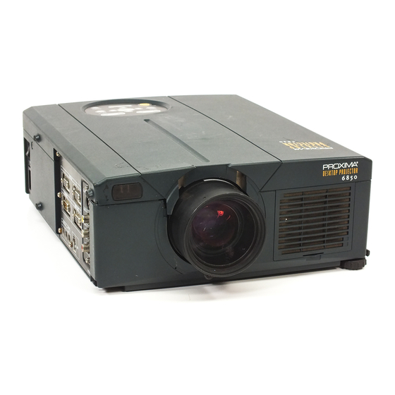
Desktop Projector
Model
DP6850
USER'S GUIDE
Thank you for purchasing the PROXIMA Desktop projector. Please read this user's manual
thoroughly to ensure correct usage through understanding. After reading, store this instruction
manual in a safe place for future reference.
Outline
The DP6850 is bright enough to fill a room
and versatile enough to fulfill your demanding
needs. Its superb image quality and advanced
video capabilities make it a dependable tool
for classrooms and meeting rooms.
Features
(1) Digital keystone correction makes it easy to
p roject a square image and increases
placement possibilities.
(2) Bright images make it ideal for conf e r e n c e
rooms and classrooms
(3) True XGA (1024 x 768) resolution and Fit-to-
V i ew® display of VGA (640 x 480) thr o u g h
SXGA (1280 x 1024) supports full screen
images from PCs and Macintosh computers
(4) Flexible connectivity with ports for up to two
computers and USB mouse
(5) High-quality video performance with picture-
in-picture and support for most video formats
(6) Motorized zoom and focus offers flexibility in
projector placement, while digital zoom offers
close-up views of selected items
Contents
Before Use .......................................3
Checking the package Contents ............8
Names and functions of each part .........8
Installation .......................................12
Basic operations ..............................13
Adjustments and functions ..................17
terminals ...........................22
terminal ...........................22
Connecting to the USB cable ...............25
terminal ...........................26
Example of system setup ..................31
Cleaning the air filter ........................31
.......................................32
Lamp
Message table .................................32
Troubleshooting .................................33
Specifications .................................34
after-service .....................35
Page
1
Advertisement
Chapters
Table of Contents

Related Manuals for Proxima Proxima DP6850


Summary of Contents for Proxima Proxima DP6850
-
Page 1: Table Of Contents
Desktop Projector Model DP6850 USER’S GUIDE Thank you for purchasing the PROXIMA Desktop projector. Please read this user’s manual thoroughly to ensure correct usage through understanding. After reading, store this instruction manual in a safe place for future reference. Outline... - Page 2 About Trademarks • VGA and XGA are trademarks of IBM (International Business Machines Corporation). • Macintosh is a registered trademark of Apple Computer Corporation of the U.S. • VESA and SVGA are trademarks or registered trademarks of Video Electronics Standards association. •...
-
Page 3: Before Use
WARNING: This equipment has been tested and found to comply with the limits for a Class A digital device, pursuant to Part 15 of the FCC Rules. These limits are designed to provide reasonable protection against harmful interference when the equipment is operated in a commercial environment. This equipment generates, uses, and can radiate radio frequency energy and, if not installed and used in accordance with the instruction manual, may cause harmful interference to radio communications, Operation of this equipment in a residential area is likely to cause harmful interference in which case the user will be required to correct the... -
Page 4: Safety Precaution
Do not install on an unstable surface. • Do not install this projector on an unstable surface such as a wobbly stand or incline because this could result in the projector falling and causing injury. - Page 5 Handle the power cord with care. • Do not damage, cut, process or s t ro n g ly twist the power cord. P l a c i n g heavy objects on the power cord, heating or strongly pulling the power cord can result in damage as well as fire or electrical shock.
- Page 6 Do not block the ventilation openings of this projector. Blocking ventilation could lead to internal overheating which could result in fire. Do not place this projector on its side during use or push it into a small, poorly ventilated location. Do not...
- Page 7 When the projector is not to be used for an extended period. For safety purposes when the projector is not to be used for an extended period because of travel, etc., always disconnect the power plug from the power outlet. Also close the lens cover to prevent the lens surface being scratched.
-
Page 8: Checking The Package Contents
STANDBY / ON button Press this button to turn the power on and off. When turned off, the projector enters standby status. Refer to page 13 - 14 for details. LAMP indicator... - Page 9 Names and functions of each part (continued) Remote control I/R receiver Main power switch Used to turn the power on and off. Security slot Use with kensington lock Connecting to the AC IN jack Make sure the accesory power cord is plugged into the AC IN jack as far as it will go.
-
Page 10: Remote Control Transmitter
DISK PAD left and right during the display. (3)Off. *3 Auto adjustment function The projector automatically adjusts 4 items (V. POSIT, H. POSIT, H. PHASE, H. SIZE). When you choose AUTO (move the cursor to the right from the manual operation position), the AUTO confirmation menu shown below is indicated. -
Page 11: Loading The Batteries
Battery usage cautions • Use only the specified batteries with this projector. Also, do not mix new and old batteries. This could cause in battery cracking or leakage, which could result in fire or personal injury. -
Page 12: Installation
2. After adjusting the projection angle, firmly lock the adjusters. 3. Rotate the adjusters for fine adjustment. • Do not release the locks unless the projector is being held; otherwise, the projector could overturn or the fingers could get caught and cause personal injury. -
Page 13: Basic Operations
Basic operations To project Turn on the main power switch of the projector [ I: ON]. • The Power indicator lights orange. Press the STANDBY / ON button. • The Power indicator will blink green and then light green. • The green blinking indicates warmup. -
Page 14: Turning Off The Power
Plug & Play This projector is VESA DDC 1 and DDC 2B compatible. Plug & play is possible by connecting to a computer that is VESA DDC (Display Data Channel) compatible to RGB 1. (Plug & play is a system configured with peripheral equipment including a computer and display, and an operating system. -
Page 15: Freeze Function
Basic operations (continued) Freeze function This function is used to freeze the image being displayed. (refer to page 10) Press the FREEZE button. • The image being displayed will freeze. • The [ ] mark appears in the lower right corner of the screen when the Freeze function is on. Cancelling the FREEZE function Press the FREEZE button. -
Page 16: Magnify Function
Basic operations (continued) Magnify function Part of an image can be displayed magnified. (refer to page 10) Press the MAGNIFY • The center part of the image will be displayed magnified approximately 2x. Changing the magnification ratio Press the MAGNIFY •... -
Page 17: Adjustments And Functions
• The selected menu item will be displayed in orange. Adjust the selected menu item with the MENU ( buttons of the projector or the DISK PAD button of the remote control. • The selected menu item will be displayed in orange. -
Page 18: Using The Setup Menu
(COLOR BALANCE Blue) Using the SETUP Menu Move the cursor to the item to be adjusted and move the MENU button of the projector or the DISK PA D button of the remote control to change the length of the bar display. - Page 19 Adjustments and functions (continu e d ) INPUT The INPUT menu is used to select RGB signal sync signal frequency of the monitor and the VIDEO signal. Adjustment item VIDEO Adjustment description Displays the following RGB inputs fH: horizontal sync frequency fV: vertical sync frequency Sets the video signal system.
- Page 20 Adjustments and functions (continu e d ) IMAGE Projection image inversion, etc., can be selected from the IMAGE menu. Adjustment item KEYSTONE Sets vertical or horizontal inversion of the projected image. H: horizontal inversion only MIRROR V: vertical inversion only H&V: both horizontal and vertical inversion.
- Page 21 Adjustments and functions (continu e d ) Communication functions, etc., can be set from the OPT menu. Adjustment item COM. SPEED Sets the communication speed (5 steps). Sets the bit configuration for the communication data. COM. BITS 7N1...7 data bits, No parity, 1 stop bit. 8N1...8 data bits, No parity, 1 stop bit.
-
Page 22: Connection To The Video Signal Terminals
Connection to the video signal terminals 1. Input signals S-VIDEO signal VIDEO signal Input Audio signal Output 2. Signal input jacks The priority sequence of the video input jacks is as follows. (1) S-VIDEO input jack When video signals are being projected, the audio input by the video is output to the audio output jack (RGB/VIDEO). -
Page 23: Example Of Computer Signal
80.0 Note 1: The Mac adapter is required for some Mac modes. Projector is compatible with 13 inch mode and 16 inch mode. Mac 13" mode=switch 1 and switch 2 are ON. Mac 16" mode=switch 2 and switch 4 are ON. - Page 24 Connection to the RGB signal terminal (continued) 4. Initial set signals The following signals are used for the initial settings. The signal timing of some computer models may be different. In such case, refer to pages 17 and 18 and adjust the V.POSIT and H.POSIT of the menu.
-
Page 25: Connecting To The Usb Cable
1. Connect the projector and computer with a suitable commercially available cable. Disconnect the mouse cable from the projector. 2. Press the INPUT button of the projector or the RGB 1/2 button of the remote control and select the input where the computer is to be connected. -
Page 26: Connection To The Control Signal Terminal
(2)Turn on the main switch of the projector (the POWER indicator lamp will light green). (3) Press the INPUT button of the projector or the RGB button of the remote control and select the input where the computer is to be connected. - Page 27 Connection to the control signal terminal (contin u e d ) CONTROL signal jack Mouse Pin no. RS-232C PS/2 DATA DATA SELO SELO Serial mouse Projector ADB (Mac) mouse Serial Projector SELO Mouse cable (ADB) (option) Computer Mouse cable (serial) (option) Computer Mouse Computer...
-
Page 28: Rs232C Communication
(1) Turn off the projector and computer power supplies and connect with the RS232C cable. (2) Turn on the computer power supply and, after the computer has started up, turn on the projector power supply. (3) Refer to page 21 and set the communication speed and the number of communication bits. -
Page 29: Command Data Chart
• The first byte of a command indicates the command type with 3 bits on the MSB side and the data length with 4 bits on the LSB side. Projector - computer ‘0xH’ : Error code ‘1xH’ : response code ‘70H’... - Page 30 When the data length is greater than indicated by the data length code, the projector will ignore the excess data code. Conversely, when the data length is shorter than indicated by the data length code, an error code will be returned to the projector.
-
Page 31: Example Of System Setup
Refer to the instruction manual of each device before connecting. Cleaning the Air filter Clean the air filter about every 100 hours . Turn off the MAIN POWER switch of the projector and pull out the power cord. Remove the front air filter. -
Page 32: Message Table
When used for an extended time, the images may become darker and the colors may deteriorate. A malfunction could occur if the projector is used in this condition, so replace the lamp with a new one. The following indicator or a message which appears when the power is turned on will indicate when the lamp should be replaced. -
Page 33: Troubleshooting
*1: When the cooling fan is stopped and the interior becomes overheated, the power will turn off automatically to allow cooling (the indicator will turn off). In such cases, turn off the projector power, allow the set to cool and then turn the projector power on again. The lamp will then light. If the lamp does not light, contact your dealer or service company. -
Page 34: Specifications
Compatibility H. Sync. Range V. Sync. Range Keystone correction Noise rating · These specifications are subject to change without notice. Desktop Projector DP6850 Three liquid crystal panels, three primary color system. 3.3 cm (1.3 Inch) TFT active matrix 768 vertical) Zoom lens F=1.7~2.3 f=49~64mm... -
Page 35: About The Warranty And
Specifications (continued) Dimensional Diagram Unit: inches About the warranty and after-service About the warranty A warranty is provided for this product. Fill in the necessary items and store in a safe place. About after-service When a problem occurs, please check first using the Troubleshooting Chart provided in this instruction manual. If the problem still persists, contact your dealer or service company. -
Page 36: Limited Warranty
About the warranty and after-service (continued) Limited Warranty Proxima Corp. (“Proxima”) warrants that each Desktop Projector 6850 (“Product”) projector purchased from Proxima Corp. is free from defects in materials and workmanship under normal use during the warranty period said warranty shall commence on the day of purchase by the End-User and continue for a period of two (2) years. - Page 37 Desktop-Projektor Modell DP6850 BEDIENUNGSANLEITUNG Herzlichen Glückwunsch zum Kauf dieses Desktop-Projektors von PROXIMA. Bitte lesen Sie diese Bedienungsanleitung zugunsten der korrekten Bedienung aufmerksam. Bewahren Sie die Anleitung anschließend für späteres Nachschlagen an einem sicheren Platz auf. Kurzbeschreibung Der DP6850 ist hell genug zur Füllung eines Raumes und vielseitig genug zur Erfüllung ihrer hohen Ansprüche.
-
Page 39: Vor Der Inbetriebnahme
Vor der Inbetriebnahme <Vor dem Betrieb> Bedeutung der Symbole WARNUNG VORSICHT Typische Symbole Zugunsten der korrekten Bedienung des Geräts befinden sich in dieser Anleitung sowie auf dem Projektor selbst bestimmte Symbole, die auf Sicherheitsrisiken und entsprechende Vorsichtsmaßregeln hinweisen, um Körperverletzungen und Sachschäden zu vermeiden. Die Bedeutung dieser Symbole ist nachfolgend erklärt. - Page 40 [Sicherheitshinweise] Bei Auftreten von Betriebsstörungen • Bei fremden Gerüchen oder Rauchentwicklung kann eine Fortsetzung des Betriebs zu Bränden oder elektrischen Schlägen führen. Schalten Sie das Gerät in diesem Fall sofort aus, und ziehen den Netzstecker aus der Steckdose. Wenden Sie sich anschließend zwecks Reparatur an Ihren F a c h h ä...
- Page 41 Den Projektor niemals in einen Behälter stellen, der Flüssigkeit enthält. Stellen Sie niemals Blumenva s e n , B l u m e n t ö p fe, Tassen, Ko s m e t i k a oder Flüssigkeiten jeglicher Art auf den Pro j e k t o r.
- Page 42 N i cht auf den Projektor setzen und keine s chweren Gegenstände darauf abl e ge n . • N i cht auf den Projektor setzen. Der Projektor kann hierdurch umfallen und Ve r l e t z u n g e n verursachen.
- Page 43 • Den Netzstecker niemals durch Ziehen am Kabel von der Steckdose trennen. Brände oder elektrische Schläge ausgelöst werden. Den Netzstecker deshalb stets am Stecker haltend aus der Steckdose ziehen. Wenn der Projektor längere Zeit nicht benutzt wird: Wird der Projektor, z.B. aufgrund einer bevorstehenden Reise o.
-
Page 44: Überprüfung Des Lieferumfangs
Überprüfung des Lieferumfangs Den Kartoninhalt überprüfen und vergewissern, daß alle Teile vollständig vorhanden sind. Falls Teile fehlen, bitte an Ihren Fachhändler wenden. Projektor 3 - S t e c k e r Netzkabel 3 110V-USA 220V-Grofßbritannien, V i d e o / A u d i o - k a b e l Europa Bezeichnung und Funktion der Teile Projektor... - Page 45 Bezeichnung und Funktion der Teile (Fortsetzung) Infrarotempfänger für Fernbedienung Hauptnetzschalter Dient zum Ein- und Ausschalten des Geräts Hauptnetzschalter Sicherheitsschlitz Mit Kensington-Schloß verwenden Netzeingangsbuchse (AC IN) Dient zum Anschließen des Zusatznetzkabels. Anschluß an die Netzeingangsbuchse (AC IN) Darauf achten, den Stecker des Zusatznetzkabels so weit wie möglich in die Buchse AC IN einzuschieben.
- Page 46 Bezeichnung und Funktion der Teile (Fortsetzung) Fernbedienungsteil VIDEO-, RGB-Taste Diese Taste dient zum Wählen der Eingangsquelle (siehe Seite 13, 19). Bereitschafts-/Ein-Taste (STANDY/ON) Diese Taste dient zum Ein- und Ausschalten der Netzversorgung. 1 Sekunde oder länger drücken, um das Gerät auszuschalten (auf Bereitschaftsbetrieb). (Siehe Seite 13 und 14) Steuerfläche (DISK PAD) / LINKE MAUS-Taste (1) Dient zum Wählen von Menügegenständen...
- Page 47 Bezeichnung und Funktion der Teile (Fortsetzung) • Die automatische Einstellung kann bis zu 30 Sekunden in Anspruch nehmen. • Auto-Einstellung arbeitet möglicherweise in bestimmten Situationen nicht korrekt, je nach angeschlossenem Computer und Signal. • Immer sicherstellen, daß die Bilder auf Vollgröße ausgedehnt werden, wenn Bilder mit niedriger Auflösung gezeigt werden. •...
-
Page 48: Aufstellung
Aufstellung Typische Aufstellung von LCD-Projektor und Leinwand Mit Hilfe dieser Abbildung die Größe der Leinwand und deren Entfernung zum Projektor bestimmen. Aufsicht Leinwand Bilddiagonale (Zoll) Minimal Verwendung der Fußversteller Den Projektionswinkel mit Hilfe der Fußversteller wie gewünscht einstellen. Frontansicht Fußversteller 1. -
Page 49: Grundlegende Bedienung
Grundlegende Bedienung Projizieren von Bildern Das Gerät mit dem Hauptnetzschalter am Projektor einschalten [ I: ON]. • Die Betriebsanzeige (POWER) leuchtet orange. Die Taste STANDBY / ON drücken. • Die Betriebsanzeige (POWER) blinkt grün und leuchtet anschließend grün. • Grünes Blinken zeigt die Aufwärmphase an. Den Objektivdeckel abnehmen. - Page 50 Grundlegende Bedienung (Fortsetzung) Ausschalten der Netzversorgung Die Taste STANDBY / ON etwa 1 Sekunde lang drücken. • Die Power - Anzeige blinkt orange, dann schaltet sich die Lampe aus. Etwa eine Sekunde später leuchtet die Anzeigelampe orange. • Nach dem Ausschalten der Netzversorgung kühlt die Lampe etwa 1 Minute lang ab. Das Gerät kann während dieser Dauer nicht ausgeschaltet werden, auch nicht durch Drücken der Taste STANDBY / ON.
- Page 51 Grundlegende Bedienung (Fortsetzung) Festhalten-Funktion Diese Funktion dient zum Festhalten des gezeigten Bildes. (siehe Seite 10) Die FREEZE-Taste drücken. • Das gezeigte Bild wird festgehalten. • Die Markierung [ ] erscheint in der rechten unteren Ecke des Bildschirms, wenn die FREEZE- Funktion eingeschaltet ist.
- Page 52 Grundlegende Bedienung (Fortsetzung) Vergrößerungsfunktion Ein Teil eines Bildes kann vergrößert gezeigt werden. (siehe Seite 10) Die Taste MAGNIFY • Die Bildmitte wird ca. 2fach vergrößert dargestellt. Ändern des Vergrößerungsverhältnisses Die Taste MAGNIFY • Wenn diese Taste gedrückt wird, wird das Bild noch größer gezeigt. Die Taste MAGNIFY •...
-
Page 53: Einstellungen Und Funktionen
Einstellungen und Funktionen 1, 3 Die MENU-Tasten ( MENU am Fernbedienungsteil drücken. • Das Menübild erscheint. • Einzelheiten siehe Seite 18 - 21. Zum Wählen des einzustellenden Menüge genstands die MENU-Tasten ( PAD am Fernbedienungsteil drücken. • Der gewählte Menügegenstand wird in orange angezeigt. R i chten Sie den gewählten Menüg e genstand mit den “MENU”... - Page 54 E i n s t e l l u n gen und Funktionen (Fort s e t z u n g ) EINRICHTUNG Bilder und Anzeigepositionen können auf dem SETUP-Menü eingestellt werden. RGB-Signaleingang Einstellgegenstand LAUTST. HELLE (HELLIGKEIT) KONTRAST SCHÄRFE FARBE F-TON V-POSIT (V-POSITION)
- Page 55 E i n s t e l l u n gen und Funktionen (Fort s e t z u n g ) INPUT Das Eingabe-Menü (INPUT) dient zum Wählen der RGB-Signal-Sync-Frequenzen von Monitor und VIDEO-Signal. Einstellgegenstand VIDEO Beschreibung der Einstellung Zeigt die folgenden RGB-Eingänge: fH: horizontale Sync-Frequenz fV: vertikale Sync-Frequenz...
- Page 56 E i n s t e l l u n gen und Funktionen (Fort s e t z u n g ) IMAGE Auf dem IMAGE-Menü kann die Inversion des Projektionsbilds usw. gewählt werden. Einstellgegenstand TRAPEZ Stellt die vertikale oder horizontale Inversion des projizierten Bilds ein. H: Nur horizontale Inversion SPIEGEL V: Nur vertikale Inversion...
- Page 57 E i n s t e l l u n gen und Funktionen (Fort s e t z u n g ) Auf dem OPT-Menü können Datenaustauschfunktionen usw. eingestellt werden. Einstellgegenstand KOM-GSCHW Stellt die Geschwindigkeit für den Datenaustausch ein (5 Stufen). Stellt die Bit-Konfiguration für die Datenübertragung ein.
-
Page 58: Video-Eingangsbuchsen
A n s chluß an die Video-Eingangsbu ch s e n 1. Eingangssignale S-VIDEO-Signal VIDEO-Signal Eingang Audio signal Ausgang 2. Signaleingänge Die Prioritätsfolge der Video-Eingangsbuchsen ist wie nachstehend angegeben: (1) S-VIDEO-Eingangsbuchse Bei Projektion einer Videoprogrammquelle geht der Ton dieser Videoquelle aus der Audiobuchse (RGB/VIDEO) aus. - Page 59 Anschluß an die RGB-Buchse (Fortsetzung) 3. Beispiel eines Computersignals Auflösung (kHz) 24,8 37,9 37,9 37,9 31,5 35,0 37,9 37,5 43,3 35,2 37,9 48,1 46,9 53,7 49,7 1024 48,4 1024 56,5 1024 60,0 1024 67.8 1152 67.5 1280 60.0 1280 1024 64.0 1280 1024...
- Page 60 Anschluß an die RGB-Buchse (Fortsetzung) 4. Anfangseinstellungssignale Die folgenden Signale werden für die Anfangseinstellungen verwendet. Die folgenden sind die Anfangs-Signaleinstellungen. Die Signalzeitgabe einiger Computermodelle kann unterschiedlich sein. In diesem Fall siehe Seite 17 und 18 zur Einstellung von V.POSIT und H.POSIT im Menü. Hintere Schwarzschulter b Horizontale Signalsteuerung (µs) Computer/Signal...
-
Page 61: Anschließen Des Usb-Kabels
Anschließen des USB-Kabels 1. Den Projektor und den Computer mit einem im Fachhandel erhältlichen angemessenen Kabel verbinden. Trennen Sie das Maus-Kabel vom Projektor 2. Durch Drücken der INPUT-Taste am Projektor oder der Taste RGB 1/2 am Fernbedienungsteil wählen, an welchen Eingang der Computer angeschlossen werden soll. 3. -
Page 62: Anschluß An Die Steuersignalbuchse
A n s chluß an die Steuers i g n a l bu ch s e 1. Mausfunktionen (1)Computer und Projektor mit dem jeweiligen Netzschalter ausschalten und die beiden Geräte mit dem mitgelieferten Kabel oder einem im Fachhandel erhältlichen Kabel, das hierzu geeignet ist, anschließen. (2)Den Projektor mit dem Hauptnetzschalter einschalten (die POWER - Anzeigelampe leuchtet gürn). - Page 63 A n s chluß an die Steuers i g n a l bu chse (Fort s e t z u n g ) Steuersignalbuchse (CONTROL) Maus Stift-Nr. RS-232C PS/2 DATA DATA SELO SELO Serienmaus ADB-Maus (Mac) Serial Projektor SELO Projektor Computer Mauskabel (Serienkabel) (Option) Computer...
- Page 64 A n s chluß an die Steuers i g n a l bu chse (Fort s e t z u n g ) 2. RS232C-Datenaustausch (1) Den Projektor und den Computer ausschalten und das RS232C-Kabel anschließen. (2) Den Computer einschalten, warten bis das Programm startet und dann den Projektor einschalten. (3) Hinsichtlich der Datenübertragungsgeschwindigkeit und Anzahl der Datenbits siehe Seite 21.
- Page 65 A n s chluß an die Steuers i g n a l bu chse (Fort s e t z u n g ) Gegenstand MAUS 00h=Mausfunktion deaktivieren, 01 bis 7Fh=Mausfunktion starten COMMUNICATE 0Xh=8N1, 1Xh=7N1 X0h=1200 bps, X1h=2400 bps, x2h=4800 bps, X3h=9600 bps, X4h=19200 bps POWER 3Eh=Netzversorgung Aus (Bereitschaftszustand), 3Fh=Netzversorgung Ein ZOOM...
- Page 66 A n s chluß an die Steuers i g n a l bu chse (Fort s e t z u n g ) Projektorstatusabfrage (1) Den Abfragecode ‘20H’ + ‘yyH’ vom Computer zum Projektor schicken. (2) Der Projektor überträgt den Rückmeldecode ‘1xH’ + ‘yyH’ +Daten an den Computer. Ändern der Projektoreinstellungen (1) Den Einstellcode ‘3xH’...
-
Page 67: Systemübersicht (Beispiel)
Systemübersicht (Beispiel) Computer (Notebook) Computer (Desktop) Lautsprecher (mit eingebautem Verstärker) Vor dem Anschließen alle Geräte ausschalten. Vor dem Anschließen die Bedienungsanleitung des jeweiligen Geräts durchlesen. Reinigen des Luftfilters Den Luftfilter etwa alle 100 Betriebsstunden säubern. Den Projektor mit dem Hauptnetzschalter (MAIN POWER) ausschalten und den Netzstecker abziehen. -
Page 68: Lampe
Reinigen des Luftfilters (Fortsetzung) Säubern des Luftfilters mit einem Staubsauger Wiedereinbauen des Luftfilters Wenn der Luftfilter mit Staub usw. verstopft ist, schaltet sich der Projektor eventuell automatisch aus, um einen Hitzestau im Gehäuse zu vermeiden.(Die Farbe der Anzeigelampe ändert sich in Rot.) Den Projektor niemals mit herausgenommenen Luftfilter einschalten. -
Page 69: Fehlersuche
Meldungstabelle (Fortsetzung) Anzeigen Die Betriebsanzeige (POWER), die Lampenanzeige (LAMP) und die Temperaturanzeige (TEMP) leuchten oder blinken in den folgenden Fällen. POWER-Anzeige LAMP-Anzeige Leuchtet orange Erlischt Blinkt grün Erlischt Leuchtet grün Erlischt Blinkt orange Erlischt Leuchtet rot Leuchtet rot Leuchtet rot Blinkt rot Leuchtet rot Erlischt... -
Page 70: Technische Daten
Technische Daten Produktbezeichnung Modell Anzeigemethode Flüssigkrist Größe allfeld Antriebsystem Bildpunktezahl Objektiv Lampe Lautsprecher Stromversorgung Leistungsaufnahme Betriebstemperaturbereich Abmessungen Gewicht VIDEO-Signaleingangsbuchsen RGB-Signaleingang -/Ausgangbuchsen CONTROL-Signalbuchse USB - Buchse Auflösung Kompatibilität H. Sync. Bereich V. Sync. Bereich Trapezverzerrung Rauschwertung · Änderungen bei technischen Daten und Design bleiben ohne Vorankündigung vorbehalten. Desktop-Projektor DP6850 Drei Flüssigkristallfelder, drei primäre Farbsysteme... -
Page 71: Garantie Und Kundendienst
Technische Daten (Fortsetzung) Abmessungsdiagramm Einheit: mm Garantie und Kundendienst Zur Garantie Der Projektor wird mit einer Garantie verkauft. Bitte füllen Sie die Garantiekarte aus und bewahren Sie sie an einem sicheren Platz auf. Zum Kundendienst Bitte überprüfen Sie Störungsursachen zuerst mit Hilfe der Fehlersuchtabelle in dieser Anleitung, bevor Sie das Gerät zur Reparatur einreichen. - Page 72 Garantie und Kundendienst (Fortsetzung) Eingeschränkte Garantie Die Proxima Corporation (Proxima) gewährleistet, daß jeder von Proxima Corp. gekaufte UltraLight SP1 Projektor (Produkt) unter normalem Gebrauch während der Garantiezeit frei von Material- und Verarbeitungsfehlern ist. Die Garantiezeit beginnt am Tag des Kaufes durch den Endbenutzer und erstreckt sich auf zwei Jahre. Um die Rechte des Endbenutzers gemäß...
- Page 73 Projecteur de bureau Modèle DP6850 Manuel d’utilisation Nous vous remercions d’avoir choisi un De bureau liquides PROXIMA. Nous vous recommandons de lire attentivement ce manuel pour bien assimiler le fonctionnement de l’appareil et de le conservez dans un lieu sûr pour pouvoir vous y référer ultérieurement. Aperçu Le DP6850 est suffisamment lumineux pour remplir une salle et suffisamment souple pour...
- Page 75 Avant de mettre l’appareil en marche <Avant de mettre l’appareil en marche> Explication des symboles Différents symboles sont utilisés dans le manuel de fonctionnement et sur le produit lui-même pour garantir une utilisation correcte de l’appareil, protéger l’utilisateur et le public contre les dangers éventuels ou contre les dommages matériels. Lisez attentivement la description qui en est donnée ci-après afin d’en assimiler la signification et le contenu.
- Page 76 [Consignes de sécurité] En cas de problème • L’appareil risque de prendre feu ou de provoquer des chocs électriques s’il est utilisé alors qu’il émet de la fumée ou une odeur anormale. Si cela se produit coupez immédiatement l’alimentation principale et débranchez la prise murale. Attendez que la fumée ne sorte plus et qu’il n’y ait plus d’odeur avant de contacter votre distributeur.
- Page 77 B r a n chez uniquement sur un courant à la tension indiquée B r a n chez uniquement sur un courant à la tension indiquée. Toute autre tension que celle indiquée pour l’appareil risque de provoquer un incendie ou de vous exposer à des risques d’électrocution.
- Page 78 Ne vous asseyez pas sur le pro j e c t e u r ou ne posez pas d’objets lourds dessus • Ne vous asseyez pas sur le projecteur Le projecteur risque de se renverser et d’être endommagé. Risque de blessure corporelle grave.
-
Page 79: Mises En Garde
d’électrocution. Toujours débrancher le fil en tirant sur la prise et non sur le fil. Si vous n’utilisez pas le pro j e c t e u r pendant une longue période Par mesure de sécurité il est recommandé de débrancher la prise murale dès que vous n’utilisez pas le projecteur pendant une longue période. -
Page 80: Nomenclature Et Fonctions Des Pièces
Vérification du contenu de l’emballage Vérifiez que tous les éléments ci-dessous sont contenus dans la boîte d’emballage. Contactez votre distributeur si vous constatez qu’une pièce manque. Projecteur Cordon d’alimentation 3 Câble vidéo/audio à 3 conducteurs 110V-US 220-V RU, Europe i s o l é s Nomenclature et fonction des pièces Unité... - Page 81 Nomenclature et fonction des pièces (suite) Photorécepteur infrarouge de télécommande Interrupteur général S’utilise pour allumer ou éteindre l’appareil éteint allumé Fente de sécurité. Utilisez-la avec le verrou Kensington. Raccordement à la prise AC IN Branchez bien le cordon d'alimentation accessoire à fond dans la prise AC IN.
- Page 82 Nomenclature et fonction des pièces (suite) Emetteur à télécommande Touche VIDEO, RGB Appuyez pour commuter. (voir pages 13 et 19) Touche STANDBY / ON S’utiliser pour mettre l’appareil sous tension ou l’éteindre. Pour éteindre l’appareil appuyez sur la touche pendant au moins 1 seconde (se met en attente de fonctionnement).
-
Page 83: Mise En Place Des Piles
Nomenclature et fonction des pièces (suite) • Les réglages automatiques peuvent prendre jusqu'à 30 secondes. • Le réglage automatique ne se fait pas correctement avec certains type d’ordinateurs ou de signaux. • Agrandissez les images au format plein écran lorsque vous affichez des images à faible résolution. •... -
Page 84: Installation
Installation Installation d’un projecteur ACL et d’un écran Prenez ce schéma comme référence pour déterminer la taille de l’écran et la distance de projection. Vue d’en haut Ecran Taille en diagonale de l' é cran (pouces) Minimum Utilisation des ajusteurs Réglez l’angle de projection avec les ajusteurs du bas. -
Page 85: Fonctionnement De Base
Fonctionnement de base Projection Allumez l’interrupteur général du projecteur [ I: allumé]. • Le témoin de marche devient orange. Appuyez sur la touche STANDBY / ON • Le témoin de mise en attente de fonctionnement clignote en vert et reste allumé en vert. •... - Page 86 Fonctionnement de base (suite) Pour éteindre l’appareil Appuyez sur la touche STANDBY/ON pendant environ 1 seconde • Le témoin POWER clignote en orange, puis il s’éteint. Environ 1 seconde plus tard, le témoin s’allume en orange. • Il faut environ 1 minute pour que la lampe refroidisse après avoir coupé l’alimentation électrique. Pendant ce délai, il n’est pas possible de remettre l’appareil en marche à...
- Page 87 Fonctionnement de base (suite) Arrêt sur image Cette fonction sert à immobiliser l’image affichée. (voir page 10) Appuyez sur la touche FREEZE • L’image affichée à l’écran s’immobilise. • Le signe [ ] s’affiche en bas et à droite de l’écran lorsque la fonction d’arrêt sur image est activée. Annulation de l’arrêt sur image Appuyez sur la touche FREEZE.
- Page 88 Fonctionnement de base (suite) Agrandissement Il est possible d’agrandir une partie de l’image et de l’afficher. (voir page 10) Appuyez sur la touche MAGNIFY • La partie centrale de l'image est agrandie 2x. Comment modifier le taux d’agrandissement A p p u yez sur le touche MAGNIFY •...
-
Page 89: Réglages Et Fonctions
Réglages et fonctions 1, 3 Appuyez sur les touches MENU ( sur la touche MENU de la télécommande. • L’écran du menu s’affiche (détails complémentaires pages 18 à 21). Appuyez sur les touches MENU ( sur l’orienteur à disque de la télécommande pour sélectionner le menu des paramètres à... - Page 90 R é g l ages et fonctions (suite) CONFIGURATION Le menu CONFIGURATION est utilisé pour modifier les réglages des paramètres d’image et de position. Entrée de signal RGB Paramètres VOLUME LUMINOSITE (CLARTE) CONTRASTE NETTETE COULEUR TEINTE POSITION V POSITION H PHASE H TAILLE H EQUIL.
- Page 91 R é g l ages et fonctions (suite) ENTREE Le menu ENTREE permet de sélectionner la fréquence du signal de synchronisation pour le signal RVB du projecteur et le signal VIDEO. Paramètre VIDEO Description du réglage Affichage des entrées RGB fH: fréquence de synchronisation horizontale fV: Fréquence de synchronisation verticale Configuration du système de signal vidéo.
- Page 92 R é g l ages et fonctions (suite) IMAGE Le menu IMAGE permet de sélectionner une projection d’image inversée par exemple. Paramètres DEFORMATION Pour Inverse l’image dans le sens vertical ou horizontal. H: inversion horizontale seulement MIROIR V: inversion verticale seulement H&V: inversion horizontale et verticale Pour configurer la couleur de suppression lorsque le mode BLANK ON est activé...
- Page 93 R é g l ages et fonctions (suite) Le menu OPT (options) permet de régler les fonctions de communication par exemple. Paramètres VITESSE COM. Pour régler la vitesse de communication (5 vitesses) Pour régler le format des données de transmission BITS COM.
-
Page 94: Connexion Aux Prises De
C o n n exion aux prises de signal vidéo 1. Signaux d’entrée Signal S-VIDEO Signal VIDEO Entrée Signal audio Sortie 2. Prises d’entrée de signal L’ordre de priorité des prises d’entrée vidéo est la suivante : (1) prise d’entrée S-VIDEO Dans le cas de signaux vidéo, l’entrée audio de la vidéo ressort par la prise jack de sortie audio. - Page 95 Connexion à la prise de signal RGB (suite) 3. Exemple de signal ordinateur Résolution (kHz) 24,8 37,9 37,9 37,9 31,5 35,0 37,9 37,5 43,3 35,2 37,9 48,1 46,9 53,7 49,7 1024 48,4 1024 56,5 1024 60,0 1024 67.0 1152 67.5 1280 60.0 1280...
- Page 96 Connexion à la prise signal RGB 4. Signaux de réglage d’origine Les signaux utilisés pour les réglages d’origine sont indiqués ci-après. Sur certains modèles d’ordinateur la commande du rythme de signal diffère. Il faudra dans ce cas régler la position verticale et la position horizontale conformément aux indications de la page 17 et 18.
-
Page 97: Connexion Au Système Câble Usb
Connexion au système câble USB 1. Raccordez le projecteur et l'ordinateur à l'aide d'un câble en vente dans les magasins. Débranchez le câble de souris du projecteur. 2. Sélectionnez l’entrée sur laquelle devra être connecté l’ordinateur en appuyant sur la touche INPUT du projecteur ou sur la touche RGB de la télécommande. -
Page 98: Connexion À La Prise De Signal
C o n n exion à la prise de signal de commande 1. Fonctionnement de la souris (1) Coupez l’alimentation principale du projecteur et de l’ordinateur. Connectez les deux unités avec le câble fourni ou un câble en option vendu dans le commerce. Débranchez le câble USB du projecteur. (2)Remettez le projecteur sous tension (Le témoin POWER s’allume en vert.). - Page 99 C o n n exion à la prise de signal de commande (suite) Prise de signal de COMMANDE Souris N° de broche RS-232C PS/2 DATA DATA SELO SELO Souris en série Projecteur Souris ADB (Mac) Serial Projecteur SELO Câble de souris (ADB) (en option) Ordinateur Câble de souris (série) (en option) Ordinateur...
- Page 100 C o n n exion à la prise de signal de commande (suite) 2. Communication RS232C (1) Couper l’alimentation principale de l’ordinateur et du projecteur. Branchez le câble RS232C. (2) Remettez l’ordinateur sous tension, lancez l’ordinateur, puis remettez le projecteur sous tension. (3) Réglez la vitesse de communication et le nombre de bits de communication conformément aux indications de la page 21.
- Page 101 C o n n exion à la prise de signal de commande (suite) Commande SOURIS 00h=souris invalidée, 01 - 7Fh=démarrage souris COMMUNIQUER 0Xh=8N1, 1Xh=7N1 X0h=1200bps, X1h=2400bps, X2h=4800bps, X3h=9600bps, X4h=19200bps ALIMENTATION 3Eh=Hors tension (attente de fonctionnement), 3Fh=sous tension ZOOM 01-3fH=zomm+, 41 - 7Fh=Zoom – MISE AU POINT 01- 3Fh=mise au point+, 41 - 7Fh=Mise au point –...
- Page 102 C o n n exion à la prise de signal de commande (suite) Interrogation sur le statut du projecteur (1) Envoyez le code d’interrogation ‘20H’ + ‘yyH’ de l’ordinateur vers le projecteur. (2) Le projecteur renvoi le code de réponse ‘1xH’ + ‘yyH’ +données vers l’ordinateur. Modification des réglages du projecteur (1) Envoyez le code de réglage ‘3xH’...
-
Page 103: Exemple De Configuration
Exemple de configuration Ordinateur (portable) Ordinateur (de bureau) Haut-parleurs (avec ampli incorporé) Avant de connecter, coupez l’alimentation électrique principale de tous les dispositifs. Avant de connecter, consultez le manuel d’entretien de chaque dispositif Nettoyage du filtre à air Nettoyez le filtre à air toutes les 100 heures d’utilisation. Coupez l’alimentation principale du projecteur et débranchez la prise murale. -
Page 104: Tableau Des Messages D'information
Nettoyage du filtre à air (suite) Passez l’aspirateur sur le filtre à air. Remettez le filtre à air en place. Le projecteur s’éteint quand le filtre à air est bouché par la poussière par exemple, ceci afin d’empêcher la température interne de monter. (Le témoin devient rouge.) N’utilisez jamais le projecteur sans son filtre. -
Page 105: Dépannage
Tableau des messages d’information (suite) Témoins Les témoins de MARCHE, de LAMPE et de TEMP s’allument ou clignotent dans les cas suivants. Témoin de Témoin de MARCHE LAMPE S’allume en orange S’éteint Clignote en vert S’éteint S’allume en vert S’éteint Clignote en orange S’éteint S’allume en rouge... -
Page 106: Caractéristiques Techniques
Caractéristiques tech n i q u e s Désignation du produit Modèle Affichage Panneau cristaux Taille liquides Alimentation Nombre de pixels 786.432 pixels ( 1.024 horizontal x 768 vertical) Objectif Lampe Haut-parleurs Alimentation électrique Consommation électrique Gamme de température de fonctionnement Taille Poids (masse) Prises d’entrée du signal vidéo... -
Page 107: Garantie Et Service Après-Vente
Caractéristiques techniques (suite) Schéma côté Unité : mm Garantie et service après-vente Garantie Ce produit est accompagné d’une garantie. Remplissez le formulaire et conservez-le en lieu sûr. Service après-vente En cas de panne, consultez d’abord le tableau de dépistage contenu dans ce manuel. Si le problème persiste contactez votre distributeur ou la société... - Page 108 Garantie et service après-vente (suite) Garantie limitée Proxima Corporation ( Proxima ) garantit tout projecteur UltraLight SP1 ( le produit ) acheté auprès de Proxima contre tout vice de forme et de matière dans des conditions d’utilisation normales pendant la période de garantie, soit deux (2) ans à compter de la date d’achat du produit par l’utilisateur final.
- Page 109 Proiettore di tipo desktop Modello DP6850 GUIDA DELL’UTENTE Vi ringraziamo per aver acquistato il proiettore di tipo desktop PROXIMA. Vi preghiamo voler leggere attentamente il manuale dell’utente in modo tale da poter comprendere quanto riportato ai fini di un corretto utilizzo del proiettore. Una volta terminata la lettura del manuale, conservatelo in luogo sicuro per future eventuali necessità.
-
Page 111: Prima Dell'utilizzo
Prima dell’utilizzo <Prima dell’utilizzo> Simboli Nel presente manuale di istruzioni e sui prodotti stessi sono utilizzati diversi simboli atti a garantire un corretto utilizzo, evitare rischi per l’utente e per le altre persone, nonché evitare danni alla proprietà. I significati di questi simboli sono qui di seguito riportati. - Page 112 [Norme di sicurezza] In caso di problemi • Continuare ad utilizzare l’apparecchio, anche nel caso in cui si percepisse la presenza di fumo o di strani odori, potrebbe essere causa di incendi o scosse elettriche. In questi casi, disattivare immediatamente il pulsante di alimentazione elettrica, quindi scollegare la spina dalla presa di corrente.
- Page 113 Non posizionare il proiettore in un contenitore con liquido. Non a p p o ggiare vasi di fiori, fioriere, contenitori, cosmetici, liquidi tipo acqua, ecc. sulla par t e superiore del pro i e t t o r e. versamenti potrebbero essere causa di incendi o scossa elettrica.
- Page 114 Non sedersi o appoggiare ogg e t t i pesanti sul proiettore. • Non sedersi sul proiettore Questo potrebbe arrecare ribaltamenti, causa di danni o lesioni personali. Porre particolare attenzione nelle abitazioni con presenza di bambini. • Non appoggiare oggetti pesanti sul p ro i e t t o r e L’appoggio di oggetti pesanti sul proiettore potrebbe causare una perdita di equilibrio o...
- Page 115 causando incendi o scosse elettriche. Per scollegare, afferrare sempre la spina. Nel caso in cui il proiettore non venga utilizzato per un lungo periodo. Ai fini della sicurezza, nel caso in cui il proiettore non venga utilizzato per un lungo periodo per motivi di viaggio, ecc., scollegare sempre la spina dalla presa di corrente.
-
Page 116: Verifica Del Contenuto Dell'imballo
Verifica del contenuto dell’imballaggio Verificare che tutti i componenti qui di seguito indicati siano inclusi nella confezione. In caso di mancanza di qualsiasi parte, contattare il vostro rivenditore. Unità del proiettore Cavo di alimentazione 3 Cavo video/audio 110V-US a 3 conduttori. 220V-UK, Europa Nomi e funzioni delle singole parti Unità... - Page 117 Nomi e funzioni delle singole parti (segue) Ricevitore a infrarossi del telecomando Interruttore di alimentazione principale Utilizzato per attivare e disattivare l’alimentazione. DISATTIVAZIONE ATTIVAZIONE Interruttore di alimentazione principale Scanalatura di protezione Utilizzare con una serratura Kensington. Presa jack dell’ingresso in C.A. Utilizzata per collegare il cavo di alimentazione ausiliario.
- Page 118 Nomi e funzioni delle singole parti (segue) Trasmettitore del telecomando VIDEO, Tasto RGB Premere questo tasto per commutare l’ingresso (Far riferimento alle pagine 13, 19). Tasto STANDBY / ON (Attesa / Attivazione) Premere questo tasto per attivare e disattivare l’alimentazione. Premere per 1 secondo o più per disattivare l’alimentazione (il proiettore entra in modalità...
- Page 119 Nomi e funzioni delle singole parti (segue) • La regolazione automatica può richiedere fino a 30 secondi. • La funzione di autoregolazione potrebbe, in alcuni casi, non funzionare correttamente, a seconda del tipo di computer collegato e del segnale. • Quando si visualizzano immagini a bassa risoluzione, accertarsi di averle ingrandite a tutto schermo.
-
Page 120: Installazione
Installazione Installazione di un proiettore a cristalli liquidi tipico e dello sc h e r m o Utilizzare lo schema qui di seguito riportato per determinare la dimensione dello schermo e la distanza di proiezione. Veduta dall’alto Schermo Lunghezza del l a di a gonal e del l o schermo (pol l i c i ) Minimo Utilizzo dei dispositivi di regolazione Utilizzare i dispositivi di regolazione sulla parte inferiore per regolare l’angolo di proiezione. -
Page 121: Operazioni Di Base
Operazioni di base Per proiettare Attivare l’interruttore dell’alimentazione elettrica principale del proiettore [ I: ATTIVATO]. • L’indicatore POWER arancione si illuminerà. Premere il tasto STANDBY / ON (ATTESA / ATTIVAZIONE) • L’indicatore POWER lampeggerà prima in verde, quindi in verde chiaro. •... - Page 122 Operazioni di base (segue) Disattivazione dell’alimentazione Premere il tasto STANDBY/ON (ATTESA / A T T I VAZIONE) per circa 1 sec. • L’indicatore dell’accensione lampeggia con luce arancione e poi la spia si spegne. Circa 1 secondo dopo, l’indicatore si accende con luce arancione. •...
- Page 123 Operazioni di base (segue) Funzione FREEZE (Fermo immagine) Questa funzione viene utilizzata per fermare l’immagine v i s u a l i z z a t a . (far riferimento alla pagina 10) Premere il tasto FREEZE (FERMO IMMAGINE) • L’immagine visualizzata verrà fermata. •...
- Page 124 Operazioni di base (segue) Funzione MAGNIFY (Ingrandimento) L’immagine può essere visualizzata con alcune parti ingrandite. (far riferimento alla pagina 10) Premere il tasto MAGNIFY • La parte centrale dell'immagine viene visualizzata con un ingrandimento pari a circa 2x. Variazione del rapporto di ingrandimento Premere il tasto MAGNIFY •...
-
Page 125: Regolazioni E Funzioni
Regolazioni e funzioni 1, 3 Premere i tasti MENU ( MENU sul telecomando. • Verrà visualizzata la schermata del Menu. Per maggiori dettagli al riguardo, far riferimento alle pagine 18 - 21. Premere i tasti MENU ( ( C U S C I N E T TO DISCO) sul telecomando per selezionare la voce di m e nu da regolare. - Page 126 Regolazioni e funzioni (segue) IMPOSTAZIONE Le immagini e le posizioni di visualizzazione possono essere regolate dal Menu SETUP (IMPOSTAZIONE). Ingresso segnale RGB Voce soggetta a regolazione VOLUME LUMINOSO (LUMINOSITA’) CONTRASTO NITIDEZZA COLORE TONALITA’ (TINT) POSIZIONE VERT. (V.POSIT) POSIZIONE ORIZZ. FASE ORIZZ.(H.PHASE) DIMENSIONE ORIZZ.(H.SIZE) BILANCIAMENTO COLORE R (BILANCIAMENTO COLORE Rosso)
- Page 127 Regolazioni e funzioni (segue) INGRESSO Il menu INPUT (INGRESSO) viene utilizzato per selezionare la frequenza del segnale di sinc. del segnale RGB del monitor ed il segnale VIDEO. Voce soggetta a regolazione VIDEO Descrizione della regolazione Visualizza i seguenti ingressi RGB (fH: frequenza di sincr.
- Page 128 Regolazioni e funzioni (segue) IMMAGINE E’ possibile selezionare l’inversione dell’immagine di proiezione, ecc. dal Menu IMAGE (IMMAGINE). Voce soggetta a regolazione Riduzione distorsione trapezoidale FUNZIONE “KEYSTONE” (DISTORSIONE TRAPEZOIDALE) Imposta l’inversione verticale o orizzontale dell’immagine proiettata. O: solamente inversione orizzontale SPECCHIO V: solamente inversione verticale O&V: sia inversione orizzontale che verticale Imposta il colore da utilizzare durante la soppressione immagine a...
- Page 129 Regolazioni e funzioni (segue) OPZIONALE Le funzioni di comunicazione, ecc. possono essere impostate dal Menu OPT. Voce soggetta a regolazione VELOCITA’ DI Imposta la velocità di comunicazione (5 fasi) COMUNICAZIONE Imposta la configurazione dei dati di comunicazione. BIT DI 7N1...7 bit dati, Nessuna parità, 1 stop bit (bit di stop). COMUNICAZIONE 8N1...8 bit dati, Nessuna parità, 1 stop bit (bit di stop).
-
Page 130: Collegamento Ai Morsetti
Collegamento ai morsetti di segnale video 1. Segnali di ingresso Segnale S-VIDEO Segnale VIDEO ngresso Segnale audio Uscita 2. Prese jack dell’ingresso di segnale La sequenza di priorità delle prese dell’ingresso video è la seguente: (1) Presa jack di ingresso S-VIDEO Quando vengono proiettati i segnali video, l’ingresso audio è... - Page 131 Collegamento al morsetto del segnale RGB (segue) 3. Esempio di segnali computer Risoluzione (kHz) 24,8 37,9 37,9 37,9 31,5 35,0 37,9 37,5 43,3 35,2 37,9 48,1 46,9 53,7 49,7 1024 48,4 1024 56,5 1024 60,0 1024 67.8 1152 67.5 1280 60.0 1280 1024...
- Page 132 Collegamento al morsetto del segnale RGB (segue) 4. Segnali dell’impostazione iniziale I seguenti segnali vengono utilizzati per le impostazioni iniziali. La determinazione dei tempi di segnale, in alcuni modelli di computer potrebbe essere diversa. In questo caso, far riferimento alle pagine 17 e 18 e regolare la POSIZ. V. e la POSIZ. O. del menu. Determinazione dei tempi del segnale orizzontale (ms) Computer/Segnale VGA-1(85Hz)
-
Page 133: Collegamento Del Cavo Usb
Collegamento del cavo USB 1. Utilizzare un cavo opzionale idoneo disponibile in commercio per collegare il proiettore e il computer. Scollegare il cavo mouse dal proiettore. 2. Premere il tasto INPUT (INGRESSO) del proiettore o il RGB 1/2 del telecomando e selezionare l’ingresso a cui il computer deve essere collegato. -
Page 134: Collegamento Al Morsetto Del Segnale Di Comando (Control)
Collegamento al morsetto del segnale di comando 1. Funzioni del mouse (1) Attivare gli interruttori di alimentazione principale del proiettore e del computer e collegare le due unità utilizzando il cavo fornito in dotazione o un cavo opzionale idoneo, disponibile in commercio. Scollegare il cavo USB dal proiettore. - Page 135 Collegamento del morsetto del segnale di comando (segue) Presa jack del segnale di COMANDO Nr. di pin RS-232C PS/2 DATA DATA SELO SELO Mouse seriale Proiettore Mouse ADB (Mac) Mouse Serial Proiettore SELO Computer Cavo del mouse (seriale) (opzionale) Computer Presa jack del mouse Mini DIN a 4 pin Cavo del mouse (ADB) opzionale...
- Page 136 Collegamento del morsetto del segnale di comando (segue) 2. Comunicazione RS232C (1) Disattivare l’alimentazione elettrica al proiettore ed al computer e eseguire il collegamento utilizzando il cavo RS232C. (2) Attivare l’alimentazione elettrica al computer e, una volta avviato il computer, attivare l’alimentazione elettrica al proiettore.
- Page 137 Collegamento del morsetto del segnale di comando (segue) Particolare MOUSE 00h=unzione mouse disabilitata, Fh (frequenza di sincronizzazione) 01 - 7=abilitazione funzione mouse COMUNICAZIONE 0Xh=8N1, 1Xh=7N1 X0h=1200bps, X1h=2400bps, X2h=4800bps, X3h=9600bps, X4h=19200bps ALIMENTAZIONE (POWER) 3Eh=alimentazione disattivata (stato di attesa), 3Fh (frequenza di sincronizzazione) = alimentazione attivata. ZOOM 01 - 3 Fh (frequenza di sincronizzazione) = Zoom +, Fh (frequenza di sincronizzazione) 41 - 7 = Zoom –...
- Page 138 Collegamento del morsetto del segnale di comando (segue) Richiesta dello stato del proiettore (1) Inviare il codice di richiesta ‘20H’ + ‘ yyH’ al computer al proiettore. (2) Il proiettore rinvia al computer il codice di risposta ‘1xH’ + ‘yyH’ +dati. Variazione delle impostazioni del proiettore (1) Inviare il codice di impostazione ‘3xH’...
-
Page 139: Esempio Di Impostazione Del Sistema
Esempio di impostazione del sistema Computer (di tipo Notebook) Computer (di tipo desktop) Altoparlanti (con amplif. incorporato) Prima di iniziare, disattivare tutti i dispositivi. Prima di iniziare, far riferimento al manuale di istruzioni di ogni dispositivo. Pulizia del filtro dell’aria Pulire il filtro dell’aria ogni 100 ore. -
Page 140: Lampada
Pulizia del filtro dell’aria (segue) Pulizia del filtro dell’aria con un’aspirapolvere Installazione del filtro Nel caso in cui il filtro dell’aria risulti ostruito da polvere, ecc., l’alimentazione al proiettore potrebbe disattivarsi in modo tale da evitare un incremento della temperatura interna (Il colore della spia della lampada cambia in rosso). -
Page 141: Guida Alla Soluzione Dei Problemi Di Funzionamento
Tabella messaggi (segue) Indicatori L’indicatore di ALIMENTAZIONE, la spia luminosa e l’indicatore della TEMPERATURA si illumineranno o lampeggeranno nei casi seguenti: Indicatore di Indicatore di ALIMENTAZIONE LAMPADA Si illumina in arancione Si spegne Si spegne Lampeggia in verde Si illumina in verde Si spegne Lampeggia in arancione Si spegne... -
Page 142: Dati Caratteristici
Dati caratteristici Nome del prodotto Modello Metodo di visualizzazione Pannello a Dimensioni del pannello. cristalli liquidi. Sistema di comando. Numero di pixel Obiettivo Lampada Altoparlante Alimentazione elettrica Potenza assorbita Campo della temperatura d’esercizio Dimensione Peso (massa) Prese jack dell’ingresso del segnale VIDEO Prese jack ingresso/uscita segnale RGB Presa jack del segnale di COMANDO (CONTROL) Spinotto a jack USB... - Page 143 Dati caratteristici (segue) Schema dimensionale Unità di misura: mm Garanzia e servizio assistenza Garanzia Questo prodotto è provvisto di garanzia. Compilare le voci interessate ed archiviare in un logo sicuro. Servizio assistenza In caso si verifichi un problema, procedere innanzitutto a dei controlli, attenendosi alla Tabella di localizzazione guasti fornita nel presente manuale di istruzioni.
-
Page 144: Garanzia Limitata
Garanzia e servizio assistenza (segue) Garanzia limitata La Proxima Corp. (“Proxima”) garantisce che ogni proiettore UltraLight SP1 (“Prodotto”) acquistato dalla Proxima Corp. è privo di difetti nei materiali e nella lavorazione in condizioni d’uso normali durante il periodo di validità della garanzia. La copertura di garanzia inizia dal giorno dell’acquisto da parte dell’utente finale e continua per il periodo di due (2) anni.
Need help?
Do you have a question about the Proxima DP6850 and is the answer not in the manual?
Questions and answers