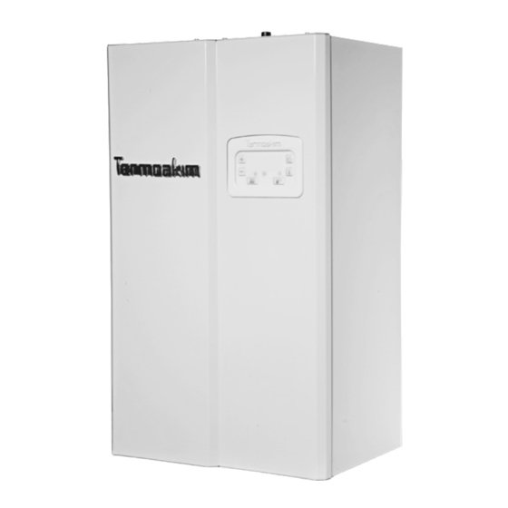
Summary of Contents for Termoakim GALAXI PRO Series
- Page 1 GALAXI PRO SERIES ELECTRIC COMBI BOILER User Manual and Warranty Certificate TS EN ISO 9001:2000 Certificate No: AQ/TR/2165...
- Page 2 Dear customer, Our company, which operates in the heating sector, continues its Research & Develop- ment activities by following the developing technology in addition to the production of electric combi boiler and floor heating very closely. We aim to make our customers benefit from the latest technology by applying technologi- cal developments to our products.
-
Page 3: Table Of Contents
CONTENTS Parts Of Electric Combi Boiler Device Installation Opening The Device Cover Installation Connection Of The Device External Hot Water Tank Connection Of The Device 6 Electrical Connection Of The Device Flooding The Device Initial Operation Of The Device Using The Control Panel Of The Device Device Error Information Electrical Connection Diagram And Panel Output Information Safety Precautions Of The Device... -
Page 4: Parts Of Electric Combi Boiler
2. Manometer 9. Mains Input Terminal 3. Boiler Heat Probe 10. Power Distribution Board 4. Resistances 11. Automatic Air Release 5. Expansion Tank 12. Recirculation Pump 6. Boiler Body 13. Fill Valve 7. Air Purger 14. 3 Bar Safety Valve www.termoakim.com... -
Page 5: Device Installation
WARNING: It is the customer’s responsibility to assemble the device in accordance with the standards specified in the user manual. 20 CM 20 CM Minimum clearance values to be left around the device. www.termoakim.com... -
Page 6: Opening The Device Cover
In order to open the cover, as seen in the picture below, • the bolts at the bottom of the device are unscrewed, the lower part of the cover is pulled towards us and push up the cover is removed from its place. Cover opening shape and direction. www.termoakim.com... -
Page 7: Installation Connection Of The Device
It is the customer’s responsibility to complete the installation of the device as specified in the user guide. Manometer Water Pressure Valve 3 Bar Safety Valve Outlet R: Record P: Dirt Holders Heating Cold Heating V: Valve Going Water Return Inlet Fig 1 Fig 2 www.termoakim.com... -
Page 8: External Hot Water Tank Connection Of The Device
CONNECTION OF THE DEVICE • The Termoakım Galaxi Pro series is designed to operate in external hot water tank mode on demand. In order to use the device in external hot water tank mode, a fully transitive, three-way valve must be connected to the system and a external hot water tank heat sensor must be installed. -
Page 9: Electrical Connection Of The Device
Voltage (V) Section (mm Section (mm 230/400 1x32/3x10 2x4/4x2,5 230/400 1x40/3x16 2x6/4x2,5 4/2,5 230/400 1x50/3x16 2x6/4x2,5 2/2,5 230/400 1x63/3x20 2x10/4x4 230/400 1x63/3x25 2x10/4x4 WARNING: The values given were calculated for a maximum length of 20 m cable to be pulled. www.termoakim.com... - Page 10 Neutral and ground line are con- nected. Is shown in the figure. Phase Neutral Ground Triphase Connection Input to R S T phase ends at the input terminal. Neutral and ground line are connected. Is shown in the figure. Neutral Ground www.termoakim.com...
-
Page 11: Flooding The Device
This may also damage the device. Contact Author- ized Service. Manometer Water Pressure Valve 3 Bar Safety Valve Outlet Heating Cold Heating Going Water Return Inlet www.termoakim.com... -
Page 12: Initial Operation Of The Device
The circulation pump can be locked due to calcareous water and corrosion in devices that have not been run for 3 months or more after water pressing. The pump should be given way. For the devices in this case, contact the Authorized Service must be made before starting. www.termoakim.com... -
Page 13: Using The Control Panel Of The Device
USING THE CONTROL PANEL OF THE DEVICE LEVEL DEVICE ON/OFF INDICATORS DEGREE BUTTON INCREASE BUTTON DECREASE BUTTON BUTTON BOILER MODE HEATING CIRCULATION BOILER HEATING MODE PUMP MODE MODE BUTTON BUTTON www.termoakim.com... - Page 14 H temperature setting and the LED light above the ( ) sym- bol will start to flash. You can adjust the degree with the (+) (-) keys. Repeat this process for re-adjustment. * This setting is only valid for devices used in boiler mode. www.termoakim.com...
-
Page 15: Device Error Information
Check the input by referring to the control panel outputs section. If the error still persists, contact the service. ER6 (High Temperature Error): If the temperature of the device is 85°C and above, it gives this error. Please contact the authorized service. www.termoakim.com... -
Page 16: Electrical Connection Diagram And Panel Output Information
4 BOILER TEMPERATURE PROBE 5 BOILER HEAT PROBE 6 CONTROL PANELS 7 12V INPUT 8 220 V OUTPUT 9 CIRCULATION PUMP 10 THREE-WAY VALVE CABLE SOCKET 11 TRANSFORMER 12 SAFETY THERMOSTAT 13 INPUT TERMINAL 14 RESISTANCE PHASE OUTPUTS 15 RESISTANCE NEUTRAL OUTPUT www.termoakim.com... -
Page 17: Safety Precautions Of The Device
The voltages coming to the device are controlled. • The device’s heat probes are controlled. • The manometer of the device is checked. If there is any conges- tion, it is cleared. • The general condition and operation of the device are checked. www.termoakim.com... -
Page 18: Rules That Must Be Followed
Ministry of Customs and Trade can apply to the General Directo- rate of Consumer Protection and Market Surveillance. • Keep service form you receive from the Authorized Service. • The life of the product specified by the Customs Trade Ministry is 10 years. www.termoakim.com...


Need help?
Do you have a question about the GALAXI PRO Series and is the answer not in the manual?
Questions and answers