Table of Contents
Advertisement
Quick Links
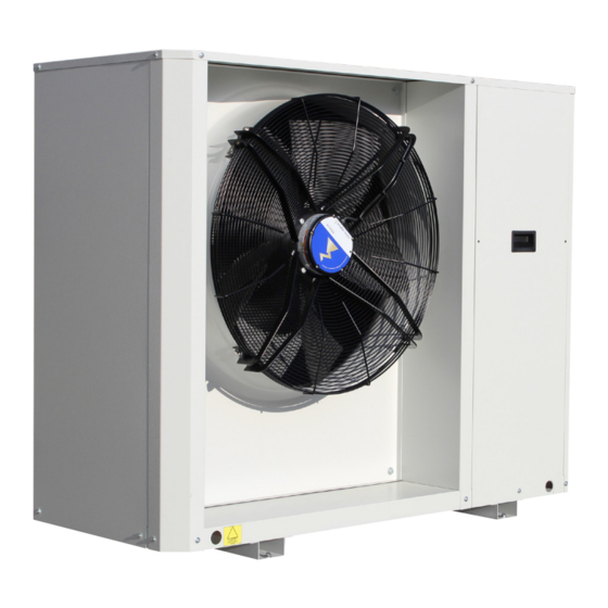
Chillers and Inverter Air/Water heat pumps with axial fan
Controller Manual
Model
021 - 026 - 028 - 032
Fonderie SIME S.p.A.
-------------------------------------------------------------------------------------------------------------------------------------------------------------------------------
This manual has been created for informative purpose. The company declines any responsibility for the results of any projecting or any installation based on the explanations and/or on the
technical specifications provided in this manual. It is besides forbidden the reproduction under any form of the texts and of the figures contained in this manual.
"This manual is a translation from the official italian language version. For reasons of environmental respect the Company will not provide the hard copy in the original language which could
be directly requested or downloaded from the Company website at any time. In case of any dispute, the original language manual will be the trusted one".
6332364 – 02/2022 – R01
Advertisement
Table of Contents

Related Manuals for Sime 021


Summary of Contents for Sime 021
- Page 1 Chillers and Inverter Air/Water heat pumps with axial fan Controller Manual Model 021 - 026 - 028 - 032 Fonderie SIME S.p.A. 6332364 – 02/2022 – R01 ------------------------------------------------------------------------------------------------------------------------------------------------------------------------------- This manual has been created for informative purpose. The company declines any responsibility for the results of any projecting or any installation based on the explanations and/or on the technical specifications provided in this manual.
- Page 2 Air/water inverter chillers and heat pumps with axial fans 07-2021 Update cap. 24 01-2021 First emission Date Compiled Approved Note Code Serie MCO01040101001.01 Chillers and Inverter Air/Water heat pumps with axial fan...
-
Page 3: Table Of Contents
Air/water inverter chillers and heat pumps with axial fans Sommario 1. PURPOSE AND CONTENT OF THE MANUAL ............... 6 1.1 HOW TO KEEP THE MANUAL ..................6 1.2 GRAPHIC SYMBOLS USED IN THE MANUAL ..............6 2. PERMITTED USE......................... 6 3. GENERAL SAFETY GUIDELINES ................... 6 3.1 PERSONAL PROTECTIVE EQUIPMENT ................ - Page 4 Air/water inverter chillers and heat pumps with axial fans 12.1.1 MEMORISING THE PROBE IN HEATING MODE ............. 16 12.1.2 HEATING MODE ON DHW STORAGE TANK ............16 12.1.3 INSUFFICIENT HEAT EXCHANGE IN A DHW SYSTEM ..........16 13.REMOTE FUNCTION ....................... 16 13.1 ON/OFF ........................16 13.2 SUMMER/WINTER MODE CHANGE .................
- Page 5 Air/water inverter chillers and heat pumps with axial fans 23.13 LACK OF VOLTAGE ....................29 23.14 UTILITIES BLOCK ALARM TABLE ................29 24.MODBUS VARIABLES ..................... 30...
-
Page 6: Purpose And Content Of The Manual
Air/water inverter chillers and heat pumps with axial fans 1. PURPOSE AND CONTENT OF THE MANUAL The purpose of the control manual for i-32 MIDI units is to provide the essential information necessary for the correct use of all the functions of the machine, in particular, it provides the essential information for the setup of unit control. -
Page 7: Personal Protective Equipment
Air/water inverter chillers and heat pumps with axial fans IS PROHIBITED: To remove and/or to manipulating any safety device. Unauthorised access to the electrical panel. To touch the systems if not autorised to do so. To performe any cleaning operation when the master switch in ‘ON’. To pull, detach or twist the appliance’s electric cable. -
Page 8: Display
Air/water inverter chillers and heat pumps with axial fans 4.1 DISPLAY 4.1.1 KEYS Select the operating mode and manually reset any alarms. Each time you press the key you have the following sequence: OFF -> COOL -> COOL+SAN* -> HEAT -> HEAT+SAN* -> OFF (*= if sanitary is enabled) During parameter settig has the function of the back key. -
Page 9: Menu
Air/water inverter chillers and heat pumps with axial fans 4.2 MENU The items controlled by the main menu are listed below. Some of this are only visible to the installer, who must access to the PSS menu to enter the password and enable higher privilege access. MENU LABEL LEVEL... -
Page 10: Digital Inputs Menu [Id]
Air/water inverter chillers and heat pumps with axial fans 4.7 DIGITAL INPUTS MENU [Id] Entering with the installer password, the status of the digital inputs can be view in this menu: 0 = input disabled 1 = input enabled --- = input not configured It is strictly PROHIBITED to disable the digital input ID1, corresponding to the flow switch. -
Page 11: System Resources
Air/water inverter chillers and heat pumps with axial fans 4. Power up the unit, setting the mains witch to the ON position; 5. Access the firmware update menu and start the procedure through the following sequence: PRG -> PSS -> PRG -> (enter installer password) ->... -
Page 12: Set-Point Modification From Analogue Input
Air/water inverter chillers and heat pumps with axial fans EXAMPLE: consider that we want to obtain the following conditions in heating mode: • set-point of 28°C with external temperature of 18°C • set-point of 45°C with external temperature of 2°C Set Hea = 28 e b08 = 1, while the other parameters will be calculated as follows: •... -
Page 13: Continuous Operation
Air/water inverter chillers and heat pumps with axial fans NOTE: The circulator switches off immediately in case of a pump blockage alarm, including a manual reset flow switch alarm The circulator remains on with automatic reset flow switch alarm even if the compressor is switched off. The circulator is always switched on if the anti-freeze resistors are operating or if the anti-freeze hydraulic pump operation is activated. -
Page 14: System Venting
Air/water inverter chillers and heat pumps with axial fans PROPORTIONAL REGULATION Speed P06/P09 ΔT [°C] In practice, in cooling mode, if the temperature difference between the inlet and outlet is greater than P09 + P10, the circulator runs at maximum speed, but if the difference is less than P09 - 0.2°C, it runs at minimum speed;... -
Page 15: Regulation In Heat Mode
Air/water inverter chillers and heat pumps with axial fans • The compressor shutdown is set by the parameter b05: the compressor shutdown when Tw,out < Tw,out,set - b05 • The compressor restart when Tw,out > (Tw,out,set + ∆T,set + b25) EXCEPTION: se ∆T,set > 8°C, the compressors restart when the discharge probe temperature is lower than the setpoint 10°C:Tw,out >... -
Page 16: Memorising The Probe In Heating Mode
Air/water inverter chillers and heat pumps with axial fans Parameter VALUE Function 0 (default) Function disabled Function active in heating and cooling mode. The remote on/off function does not disable DHW production. Function active in heating and cooling mode. The remote on/off function disables DHW production. Function active only in heating mode The remote on/off function disable DHW production. -
Page 17: Summer/Winter Mode Change
Air/water inverter chillers and heat pumps with axial fans 13.2 SUMMER/WINTER MODE CHANGE The control offers the possibility to remotely manage the operating mode of the machine in heating or cooling mode. The function can be set on digital input is settable DI2 via parameter H46: Parameter VALUE Function... -
Page 18: Minimum Hz Functions
Air/water inverter chillers and heat pumps with axial fans Parameter VALUE Function Function disabled Function configured but not active H129 Enabled only in cooling mode Enabled only in heating mode Enabled in cooling and heating mode MINIMUM HZ FUNCTIONS Configuring parameter L02=1 and L03≠0 reduces the nominal operating Hz of the compressor. Parameter VALUE Function... -
Page 19: Individual System/Health Integration Resistence
Air/water inverter chillers and heat pumps with axial fans Parameter VALUE Function DHW integration resistor Enabling of DHW resistors 10 (default) Sanitary integration activation delay (in minutes) Type of use of resistance 18.3 INDIVIDUAL SYSTEM/HEALTH INTEGRATION RESISTENCE Configuring the DHW resistance it is also possible to use it as a system resistor, by setting the parameter r15 = 2 and r24 = 3. In this way, in the event of a request for system integration, the resistance declared as DHW integration is activated, thus making it possible to have a single integration resistance for the system, DHW and defrosting. -
Page 20: Operation Heat Pump Mode
Air/water inverter chillers and heat pumps with axial fans • r22 = set for joint operation with heat pump priority • r28 = set for joint operation with priority of auxiliary units • r08 = set for replacement operation Considering the heating and/or DHW operating modes, there are 4 operating areas: INTEGRATION LOGIC Outside temp. -
Page 21: Operating Bands
Air/water inverter chillers and heat pumps with axial fans If the replacement auxiliary system is a boiler without a circulator (r32 = 0 or 2), the heat pump circulator is active when the boiler is enabled. If the auxiliary system is a boiler with its own circulator (r32 = 1 or 3), the heat pump circulator is switched off and after P01 (default 30 seconds) the boiler is enabled. - Page 22 Air/water inverter chillers and heat pumps with axial fans TABLE 2. JOINT OPERATION, BRACKET 1 INTERVENTION ORDER STATUS OPERATION 1) Heat pump 2) After r16 minutes, system integration Set the HEAT+SAN SANITARY resistence minutes 3) After further r16 minutes, boiler 1) Heat pump 2) After r16 minuti, boiler Set the...
-
Page 23: Auxiliary Systems Offset Management
Air/water inverter chillers and heat pumps with axial fans TABLE 4. OPERATIO IN SUBSTITUTION INTERVENTION ORDER STATUS OPERATION 1) Boiler Set the 2) After r12 minutes, system integration HEAT+SAN SANITARY 0/1/2 minutes resisitence 1) Sanitary integration heater Set the HEAT+SAN SANITARIO 0/1/2 2) After r12 minutes, boiler... -
Page 24: Antifreeze Protection Resistances (If Ka Accessory Is Present)
Air/water inverter chillers and heat pumps with axial fans • r30 = Temperature offset for boiler and system resistors second set point (Hea2); • r31 = temperature offset for boiler and domestic hot water heaters (San). In this way the heat pump will stop at the set point and the thermal jump, according to the set offset, will be borne by the boiler and/or the integration resistors. - Page 25 Air/water inverter chillers and heat pumps with axial fans CAUTION: • All operations with INSTALLER visibility must be carried out by QUALIFIED PERSONNEL. • Values that differ from the default values may compromise the correct operation of the machine; if in doubt about the value to be set, contact the head office.
- Page 26 Air/water inverter chillers and heat pumps with axial fans Allowed configurations: Parame- Description Unit Default Range Visibility Description Notes First cooling setpoint °C 25÷Coo2 First heating setpoint °C 45.0 Hea2÷H01 If sanitary function Sanitary setpoint °C 48.0 25÷H01 active Coo2 Second cooling setpoint °C 18.0...
- Page 27 Air/water inverter chillers and heat pumps with axial fans Allowed configurations: Parame- Description Unit Default Range Visibility Description Notes Enable dinamic setting 0÷1 See par. 6 Maximum cooling offset °C -50.0÷80.0 See par. 6 Maximum heating offset °C -3.0 -50.0÷80.0 See par.
-
Page 28: Alarms
Air/water inverter chillers and heat pumps with axial fans Allowed configurations: Parame- Description Unit Default Range Visibility Description Notes It is recommended not to change this Upper limit Joint function I °C -16÷50 Respect r22 ≥ r28 ≥ r08 value, as this could band affect the operation of the unit... -
Page 29: E691÷E701] Transducer Alarms
Air/water inverter chillers and heat pumps with axial fans 23.5 [E691÷E701] TRANSDUCER ALARMS The alarm is activated if the relevant pressure transducers are faulty or disconnected. This alarm is manual reset. 23.6 [E801] INVERTER TIMEOUT When the on-board control does not communicate with the compressor driver board, a time-out alarm is activated to avoid losing control of the system. - Page 30 Air/water inverter chillers and heat pumps with axial fans Alarm code DESCRIPTION Block E691 Low pressure transducer failure Machine E701 High pressure transducer failure Machine E711 Fault in voltage input 0-10V DC Machine E801 Inverter communication timeout Compressor E851 Inverter hardware problem Compressor E861 Motor current too high...
- Page 31 Air/water inverter chillers and heat pumps with axial fans Register Format Range Name Description Note (0) Stand by (1) Cooling (2) Heating Reading values of the machine status (4)Only sanitary mode¹ (5) Cooling + Sanitary¹ (6) Cooling + Sanitary¹ Necessary for the Enablement of writing the machine 7201 BIT MASK...
- Page 32 Air/water inverter chillers and heat pumps with axial fans Register Format Range Name Description Note °C/10 Evaporation °C/10 Condensation Temperature trans- ducer °C/10 Evporation circuit 2 °C/10 Condensation circuit2 °C/10 Water inlet °C/10 Water outlet °C/10 °C/10 Compressor inhlation °C/10 Outdoor °C/10 Compressor discharge 1...
- Page 33 Air/water inverter chillers and heat pumps with axial fans Register Format Range Name Description Note Probe 1 error E611 Probe 2 error E621 Probe 3 error E631 Probe 4 error E641 Probe 5 error E651 Probe 6 error E661 Probe 7 error E671 Probe 8 error E681...
- Page 34 Air/water inverter chillers and heat pumps with axial fans Register Format Range Name Description Note Phase sequence inverter 1 E891 Phase sequence inverter 2 E892 Phase sequence inverter 3 E893 Model error inverter 1 E901 Model error inverter 2 E902 Model error inverter 3 E903 BIT MASK...
- Page 35 Air/water inverter chillers and heat pumps with axial fans...
- Page 36 Fonderie Sime S.p.A - Via Garbo, 27 - 37045 Legnago (Vr) Tel. +39 0442 631111 - Fax +39 0442 631292 - www.sime.it...
Need help?
Do you have a question about the 021 and is the answer not in the manual?
Questions and answers