Table of Contents
Advertisement
Quick Links
Advertisement
Table of Contents

Related Manuals for Chauvin Arnoux PEL 51


Summary of Contents for Chauvin Arnoux PEL 51
- Page 1 EN - User’s manual PEL 51 PEL 52 Power & Energy Logger...
- Page 2 The product has been declared recyclable after analysis of its life cycle in accordance with the ISO 14040 standard. Chauvin Arnoux has adopted an Eco-Design approach in designing this appliance. Analysis of the complete lifecycle has enabled us to control and optimize the effects of the product on the environment. In particular, this appliance exceeds regulation requirements with respect to recycling and reuse.
- Page 3 PRECAUTIONS FOR USE This device complies with safety standard IEC/EN 61010-2-30 or BS EN 61010-2-030, the leads comply with IEC/EN 61010-031 or BS EN 61010-031 and the current sensors comply with IEC/EN 61010-2-032 or BS EN 61010-2-032 for voltages up to 600 V in category III.
-
Page 4: Table Of Contents
CONTENTS 1. GETTING STARTED ................................5 1.1. Delivery condition ................................5 1.2. Accessories .................................6 1.3. Spares ..................................6 1.4. Charging the battery ..............................6 2. DEVICE OVERVIEW ................................7 2.1. Description ...................................7 2.2. PEL51 and PEL52 ...............................8 2.3. Terminal block ................................8 2.4. Back .....................................9 2.5. SD card slot .................................9 2.6. -
Page 5: Getting Started
1. GETTING STARTED ①②③④⑤⑥⑦⑧⑨⑩⑪⑫⑬⑭⑮⑯⑰⑱⑲ 1.1. DELIVERY CONDITION ① ③ ② ④ PEL 52 POWER & ENERGY LOGGER ⑥ ⑦ ⑬ ⑤ ⑧ ⑨ ⑩ ⑪ ⑫ ... -
Page 6: Accessories
1.2. ACCESSORIES „ MiniFlex MA193 250 mm „ MiniFlex MA193 350 mm „ MiniFlex MA194 250 mm „ MiniFlex MA194 350 mm „ MiniFlex MA194 1000 mm „ MN93 clamp „ MN93A clamp „ C193 clamp „ MINI 94 clamp „... -
Page 7: Device Overview
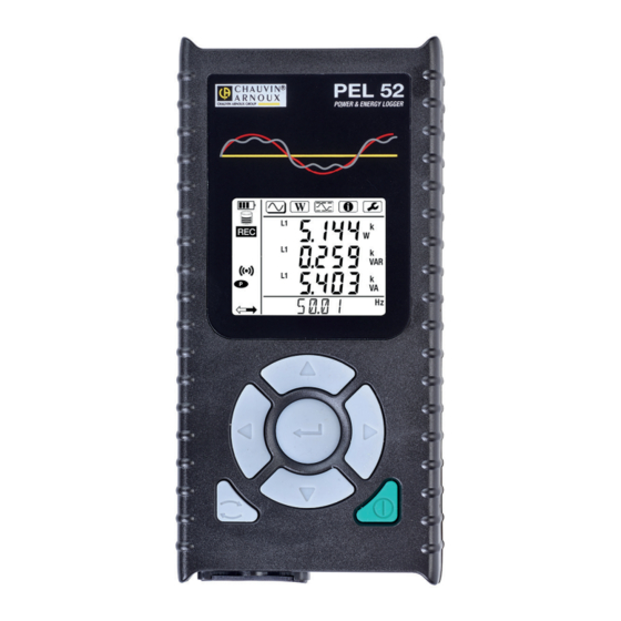
2. PRESENTATION OF THE INSTRUMENTS 2.1. DESCRIPTION PEL: Power & Energy Logger The PEL51 and PEL52 are single-phase and two-phase power and energy loggers that are easy to use. They have a large backlit LCD display and an SD card to store the measurements. The PEL makes it possible to record voltage, current, power and energy on alternating current distribution grids (50 Hz or 60 Hz). -
Page 8: Pel51 And Pel52
2.2. PEL51 AND PEL52 Measuring terminals. PEL 52 POWER & ENERGY LOGGER Backlit LCD display. Navigation keys. On / Off button. Select button. SD card slot. Figure 3 2.3. TERMINAL BLOCK PEL52 PEL51 600 V 600 V 600 V CAT III 600 V CAT III 2 voltage inputs 3 voltage inputs... -
Page 9: Sd Card Slot
2.4. REAR 4 non-slip pads. 2 magnets. Figure 5 2.5. SD CARD SLOT The PEL must not be used when the SD card slot is open. Before opening the SD card slot, disconnect the device and turn it off. To unlock the protective cap, turn the screw a quarter turn. SD card slot. -
Page 10: Set Up
2.6. MOUNTING As a recorder, the PEL is intended to be installed for a fairly long period in a technical room. The PEL must be placed in a well ventilated room whose temperature must not exceed the values specified in § 6.5. The PEL can be mounted on a flat vertical ferromagnetic surface using the magnets incorporated in its housing. -
Page 11: Memory Card
2.8.1. STATUS ICONS Icon Description Indicates battery charge status. When blinking, battery needs charging. Indicates memory card is full. When blinking, SD card is missing or locked. When blinking, a recording is scheduled. When on and steady, a recording is in progress. Indicates an out-of-range value that cannot be displayed. -
Page 12: Operation
3. OPERATION The PEL must be configured before any recording. Configuration involves the following steps: „ Establish a wifi connection with the PC (to use the PEL Transfer software, see § 5). „ Select the connection according to the type of distribution network. „... -
Page 13: Configuring The Device
3.2. CONFIGURING THE INSTRUMENT Several main functions can be configured directly on the device. For full configuration, use the PEL Transfer software (see § 5) once wifi communication has been established. To enter Configuration mode from the device, press the ◄ or ► keys until the symbol is selected. - Page 14 1) Wifi access point connection procedure The first connection must be made in wifi access point mode. „ Press the Select first. The device displays START REC. PUSH ENTER TO START RECORDING. WIFI ST. PUSH ENTER FOR WIFI ST, WIFI OFF. PUSH Press the key a second time and the device displays „...
- Page 15 If the username and password are lost, you can reset to factory configuration (see § 3.2.5) 2) Wifi connection procedure (continued) Once your device is connected to a wifi access point, you can connect it to a wifi router. This will allow you to access your device from a smartphone or tablet, or even from an IRD network through a public or private network.
- Page 16 „ In PEL Transfer, change the connection to Ethernet (LAN or wifi) and enter the IP address of your device, port 3041, UDP protocol. This lets you connect several PELs on the same network. Figure 14 Configuration of the IRD server connection „...
- Page 17 3.2.3. NOMINAL PRIMARY CURRENT Press the ▼ key to go to the following screen. Figure 16 Connect the current sensor(s). The current sensor is automatically detected by the device. For the PEL52, if two current sensors are connected, they must be identical. For AmpFlex or MiniFlex sensors, press the key to select 300 or 3000 A.
-
Page 18: Information
3.2.5. RESET Press the ▼ key to go to the following screen. Figure 18 To reset the device to the default wifi configuration (direct wifi, password deleted), press the key. The device asks for confirmation before performing the reset. Press the key to confirm and any other key to cancel. - Page 19 „ Date Year, month, day „ Time Hour, minute, second „ IP address (scrolling) „ Software version and scrolling serial number,...
-
Page 20: Use
4. USE Once the device has been configured, it is ready for use. 4.1. DISTRIBUTION NETWORKS AND CONNECTIONS OF THE PEL Connect the current sensors and voltage measurement leads on your installation according to the type of distribution network. Source Load Always check that the arrow on the current sensor is pointing towards the load. -
Page 21: Recording
4.1.3. TWO-PHASE 3-WIRE (TWO-PHASE FROM A MID-TAP TRANSFORMER): 2P-3W2I (PEL52) For two-phase 3-wire measurements with 2 current sensors: „ Connect the N measuring lead to the neutral conductor. „ Connect the V1 measuring lead to the L1 phase conductor. „ Connect the V2 measuring lead to the L2 phase conductor. „... - Page 22 4.3.1. MEASUREMENT MODE This mode displays the instantaneous values: voltage (V), current (I), active power (P), reactive power (Q), apparent power (S), frequency (f), power factor (PF), phase shift (φ). The display depends on the configured network. Press the key to switch from one screen to the next. Single-phase 2-wire (1P-2W1I) φ...
- Page 23 Single-phase 3-wire 2-currents (1P-3W2I) and two-phase 3-wire (2P-3W2I) (PEL52) φ (I φ (V φ (I φ (I Sum of powers on L1 and L2. If a current sensor is not detected, all the quantities that de- pend on this current (current, angle, powers, PF) are undefined (displays - - - - ).
- Page 24 4.3.2. ENERGY MODE This mode displays the energy: active energy (Wh), reactive energy (varh), apparent energy (VAh). The energies displayed are the total energies, of the source or of the load. The energy depends on the duration. Press the key to switch from one screen to the next. You will scroll successively: „...
- Page 25 Single-phase 3-wire 2-currents (1P-3W2I) and two-phase 3-wire (2P-3W2I) (PEL52) Sum of powers on the load on L1 and L2.
- Page 26 Sum of powers on the source on L1 and L2.
-
Page 27: Pel Transfer Software
You must have administrator rights on your PC to install the PEL Transfer software. A warning message similar to the one below appears. Click OK. There is no USB connection on the PEL 51 and 52, so ignore this automatic message which applies to other devices in the PEL range. - Page 28 A shortcut has been added to your desktop or in the Dataview directory. You can now open PEL Transfer and connect your PEL to the computer. For background information on using PEL Transfer, see the software Help.
-
Page 29: Technical Characteristics
6. TECHNICAL SPECIFICATIONS 6.1. REFERENCE CONDITIONS Parameter Reference conditions Ambient temperature 23 ± 2 °C Relative humidity 45 to 75% RH Voltage No DC component Current No DC component Phase voltage [100 Vrms; 600 Vrms] without DC (< 0.5%) Input voltage of current inputs [50 mV;... - Page 30 6.2.3. INTRINSIC UNCERTAINTY (EXCLUDING CURRENT SENSORS) With: „ R: displayed value. „ I : nominal current of the current sensor for an output of 1 V, see Table 16 and Table 17. „ P and S : active and apparent power for V = 230 V, I = Inom and PF = 1. „...
- Page 31 Quantities Measurement range Intrinsic uncertainty Sin φ = 1 V = [100 V; 690 V] ± 2% R I = [5% I ; 120% I Sin φ = [0.5 inductive; 0.5 capacitive] V = [100 V; 690 V] ± 2% R I = [10% I ;...
- Page 32 b) MiniFlex MA194 MiniFlex MA194 Nominal range 300 / 3,000 Aac 0.05 to 360 Aac for the 300 A range Measurement range 1 A to 3,600 Aac for the 3,000 A range Length = 250 mm; Ø = 70 mm Maximum clamping diameter Length = 350 mm;...
- Page 33 e) MN93 clamp MN93 clamp Nominal range 200 Aac for f ≤1 kHz Measurement range 0.1 to 240 Aac max (I >200 A non-continuous) Maximum clamping diameter 20 mm Influence of the conductor's < 0.5%, at 50/60 Hz position in the clamp Influence of an adjacent >...
- Page 34 h) Current sensor thresholds Sensor Nominal current Number of turns Display threshold C193 clamp 1000 A 0.50 A 1 turn 0.40 A 300 A 2 turns 0.21 A 3 turns 0.15 A AmpFlex A193 ® MiniFlex MA193 or MA194 1 turn 3,000 A 2 turns 3 turns...
-
Page 35: Variation In The Field Of Use
AmpFlex and MiniFlex characteristics ® Intrinsic Intrinsic Typical uncer- Current sen- Current uncertainty I nominal uncertainty tainty on φ at Resolution (RMS or DC) on φ at 50/60 Hz 50/60 Hz at 50/60 Hz [0.5 A; 10 A] 300 Aac ±... -
Page 36: Power Supply
6.3.4. CONTINUOUS COMPONENT Range of influence: ± 100 Vdc Quantities influenced: V Rejection: > 60 dB 6.3.5. FREQUENCY Range of influence: 45 Hz to 65 Hz, - 60° ≤ φ ≤ +60° Quantities influenced: V Influence: 0.1 %/Hz 6.3.6. BANDWIDTH Range of influence: 100 Hz to 5 kHz (harmonics) Presence of the fundamental at 50/60 Hz (THD = 50%) : 0.5% @ 2.1 kHz / -3 dB @ 5 kHz... -
Page 37: Environmental Characteristics
6.5. ENVIRONMENTAL CHARACTERISTICS „ Temperature and relative humidity 1 = Reference range % RH 1 + 2 = Operating range 1 + 2 + 3 = Storage range with battery T (°C) Figure 23 „ For indoor use. „ Altitude „... -
Page 38: Radio Emission
6.10. RADIO EMISSION The devices comply with the RED Directive 2014/53/EU and FCC regulations. FCC certification number for the wifi: FCC QOQWF121 6.11. MEMORY CARD Transferring a large amount of data from the SD card to a PC can take a long time. In addition, some computers can have difficulty processing such amounts of information and spreadsheets only accept a limited amount of data. -
Page 39: Maintenance
„ Comply with the conditions for storage. 7.3. UPDATING FIRMWARE In a constant concern to provide the best possible service in terms of performance and technical developments, Chauvin Arnoux offers the opportunity to update the firmware. When your device is connected to PEL Transfer via wifi, you will be informed when a new firmware version is available. -
Page 40: Warranty
8. WARRANTY Except as otherwise stated, our warranty is valid for three years starting from the date on which the equipment was sold. The extract from our General Terms of Sale is available on our website. www.chauvin-arnoux.com/en/general-terms-of-sale The warranty does not apply in the following cases: „... -
Page 41: Appendix
9. APPENDIX 9.1. MEASUREMENTS 9.1.1. DEFINITION Geometric representation of active and reactive powers: Active power Active power supplied consumed Reactive power consumed φ Reactive power supplied Figure 24 The reference of this diagram is the current vector (fixed on the right-hand part of the axis). The voltage vector V varies in its direction as a function of the phase angle φ. -
Page 42: Measurement Formulas
9.1.2.4. Calculation of energies Energies are calculated every second. Total energies are available with the data of the recorded session. 9.2. MEASUREMENT FORMULAS Quantities Formulas Comments vL = v1 or v2 incremental sample AC RMS phase-neutral voltage (V N = number of samples ab = u incremental sample AC RMS phase-phase voltage (U... -
Page 43: Supported Electrical Networks
Quantities Formula Cos (φ) of the load − ∑ Cos( ϕ × Cos( ϕ with the associated quadrant Table 19 N is the number of "1 s" values for the aggregation period considered (1, 2, 3, 4, 5, 6, 10, 12, 15, 20, 30 or 60 minutes). 9.4. -
Page 44: Values Available
9.5. VALUES AVAILABLE ● available on the instrument and in PEL Transfer ○ available in PEL Transfer not available Max value Real-time Trend value Trend value Min/Max 1s Quantities Symbol value 1s aggregated aggregated Phase-neutral voltage ● ○ ● ○ ○... - Page 45 Max value Real-time Trend value Trend value Min/Max 1s Quantities Symbol value 1s aggregated aggregated Apparent energy ● ○ on the source Apparent energy ● ○ on the load Φ ( ● Φ ( ● Φ ( ● Φ ( ●...
-
Page 46: Values Available
9.6. VALUES AVAILABLE The following quantities are available in the instrument or in PEL Transfer. PEL51 and PEL52 PEL52 Quantities 1P-2W1I 1P-3W2I and 2P-3W2I ● ● ● ● ● ● ● ● ● ● ● ● ● ● ● ● ●... -
Page 47: Glossary
9.7. GLOSSARY φ Phase offset of the voltage relative to the current. ° Degree. Percentage. Ampere (current unit). Alternative component (current or voltage). Aggregation Different averages defined at § 9.3. Current or voltage peak factor: ratio of the peak value of a signal to the effective value. cos φ... - Page 48 FRANCE INTERNATIONAL Chauvin Arnoux Chauvin Arnoux 12-16 rue Sarah Bernhardt Tél : +33 1 44 85 44 38 92600 Asnières-sur-Seine Fax : +33 1 46 27 95 69 Tél : +33 1 44 85 44 85 Our international contacts Fax : +33 1 46 27 73 89 info@chauvin-arnoux.com...
Need help?
Do you have a question about the PEL 51 and is the answer not in the manual?
Questions and answers