Table of Contents
Advertisement
Advertisement
Table of Contents

Subscribe to Our Youtube Channel
Related Manuals for Pelltech PV20a


Summary of Contents for Pelltech PV20a
- Page 1 PV20a and PV30a pellet burners User manual DK9902A1...
-
Page 2: Table Of Contents
PV20a / PV30a pellet burner 2/ 41 page Table of content Safety ................................4 Warnings ..............................4 Notice ................................4 Package contents ............................6 Description ............................7 Principal function.......................... 8 Safety devices ..........................8 Specification ..........................10 Pellets ............................10 Installation ............................ - Page 3 Annex 3 Table of parameters ......................38 Annex 4 List of languages ....................... 40 Warranty ..............................42 Manufacturer of pellet burners PV20a and PV30a: Pelltech OÜ Manufacturers address: Sära tee 3, Peetri, Rae vald, 75312 Harjumaa ESTONIA Name of product: Pellet burners PV20a and PV30a Ph..
-
Page 4: Safety
Manufacturer of burners has right to make changes in construction of burner and its firmware. Present user manual is original user manual for PV20a and PV 30a pellet burners. Pellet burners PV20a and PV30a correspond to following standarts and directives:... - Page 5 Electrical supply 230V Max heat input 20kW Emission class Noise emission 52dB Power consumption at stand-by Manufacturer: Pelltech OÜ, Sära tee 3, Peetri, Estonia Pellet burner PV 30a Year of production 2014 Electrical supply 230V Max heat input 30kW Emission class...
-
Page 6: Package Contents
PV20a / PV30a pellet burner 6/ 41 page Package contents The burner is shipped with following components included: 1. Grate 2. Burner 3. Brackets for hose (2x) 4. Flange 5. Ceramic seal 6. 7-pole boiler connector 7. Hose 8. External auger’s fixating chain DK9902A1 www.pelltech.eu... -
Page 7: Description
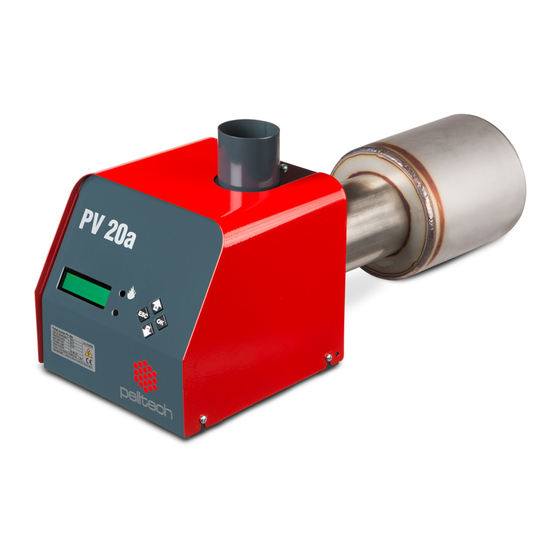
PV 20a/30a is a pellet burner that is intended to be used with 6 or 8mm diameter premium class ENPlus- A1 wood pellets. You cannot use any other fuel to run those burners. The PV20a/30a burner is connected to the boiler with a standart 90 mm flange (similar to oil burners). -
Page 8: Principal Function
Principal function The PV20a/30a burners are meant to be installed in a boiler and fuelled with wood pellets. The external auger transports the pellets from a pellet container to the burner. The controller board contains a microprocessor system that tests main safety components, monitors and regulates the burning procedure, starts and stops the burner automatically according to the boiler temperature. - Page 9 PV20a / PV30a pellet burner 9/ 41 page Figure 2 Safety devices 1.Melting hose To avoid the reaching of fire during back-burning to external auger, a melting hose is put between external auger and pellet burner. The hose will melt when air temperature in it’s inside reaches 100 2.Temperature sensor...
-
Page 10: Specification
Pellets have to be stored in a dry and ventilated room. Only premium wood pellets e.g. ENPlus-A1 can be used in PV20a/30a burners. Table 2 provides an overview of the most important wood pellet properties and threshold values. -
Page 11: Installation
PV20a / PV30a pellet burner 11/ 41 page Table 2 Wood pellets properties Raw material Sawdust,cutter shavings and stem wood Calorific value 4700-5100 kWh/ton Bulk density ca 650-670 kg/m Volume of 1 ton 1.5-1.6 m Diameter 6-8 mm Length 3-5 x diameter Fines content (<3,2 mm) - Page 12 180 or 200mm. The height of firebox must leave space at least 100mm (H1) for ash below burning chamber and 100mm above burning chamber. Minimum boiler firebox dimensions for PV20a are: L ≥350mm; H≥350mm and for PV30a L ≥400mm; H≥370mm.
-
Page 13: Installation Of The Burner To The Boiler
PV20a / PV30a pellet burner 13/ 41 page Table 3 Mounting hole measurements Measurement Unit Value ⌀D hole for burning chamber neck ⌀D1 130..150 flange bolt ring diameter ⌀D2 8..9 bolt holes Figure 6 Mounting holes with supplied flange for boiler door... - Page 14 PV20a / PV30a pellet burner 14/ 41 page Figure 9 3. Fix the flange (2) to boilers door (1). (Figure 9). Make sure that opening of flange and the opening of the boiler’s door are aligned. 4. Fix the burning chamber (8) to boilers door (1). For that you need to put a ceramic seal (4) on the narrower side of the burning chamber and then put the chamber through the door of the boiler (1) in a way that the rearward wall of the burning chamber would lean on the door of the boiler.
-
Page 15: External Auger
PV20a / PV30a pellet burner 15/ 41 page External auger The external auger transports pellets from the pellet container to the burner. The burner controls the work of the external auger. The external auger is connected to the burner with a special ∅ 60mm hose. -
Page 16: Initial Start Up
PV20a / PV30a pellet burner 16/ 41 page Notice! All electrical connections of the burner must be made by a qualified professional. 5- wire 4- wire Tt – Boiler thermostat connection connection Figure 12 Thermostat connections Figure 13 Socket connections... -
Page 17: Optional Components
PV20a / PV30a pellet burner 17/ 41 page run, the external auger may need up to 20 minutes to load. After the pellets are loaded the burner will go into IGNITION mode then PRE-BURN mode then finally BURNING mode where it will remain until it reaches the temperature by the thermostat. -
Page 18: Flue Gas Fan
PV20a / PV30a pellet burner 18/ 41 page Modem (2) is connected according to diagram on Figure 15. Power supply cable’s white wire is connected to motors wire (pin X2-8) and brown to X2-4. Adapter EP0005 cable is connected to modem and to controllers UART connector. -
Page 19: Error Output
PV20a / PV30a pellet burner 19/ 41 page During calibration burner has to be at WAITING status, all doors and windows of boiler room opened, also boiler’s door has to be opened. Error output It is possible to connect additional devices as pump, modem etc to burner which are possible to turn on or off when error occures. -
Page 20: Operation And Service
PV20a / PV30a pellet burner 20/ 41 page THM activates if PAR53 value is more than 1 and BURNING status has lasted longer than set in PAR15 (typically 30min). The burner will change its output power according to currently measured temperature and the rate of temperature change. -
Page 21: Starting And Stopping
PV20a / PV30a pellet burner 21/ 41 page More than 3 sec Resetting error status and turning burner ON More than 3 sec in menu’s Resetting pellets counter INFO submenu COUNTER More than 3 sec in NO POWER Switching burner and battery OFF... - Page 22 PV20a / PV30a pellet burner 22/ 41 page WAITING There is no Burner is turned on and waits for boiler’s thermostat switching on. time limits for waiting status. Feeder auger works periodically at WAITING time – ½ rotations after every 2 minutes. When thermostat switches on, burner goes to TESTING.
- Page 23 PV20a / PV30a pellet burner 23/ 41 page PRE-BURN The purpose of preburn mode is to fully ignite the pellets that were loaded for ignition. Pre burn has 1-4 cycles (PAR 42) of 30-80seconds (PAR 41) each. No fuel is added during the first cycle but ½ a rot of feeder auger is added between the following feeder.
-
Page 24: Output Power Levels
Feeder motor current is reached PAR46 pre-set value. GRATE ERROR Existing burners don’t have ash removal system. Error is displayed when in PAR99 wrong type of burner is selected. Select PV20a or PV30s depending on real type of burner. FAN ERROR Fan doesn’t reach 40 rps in 7 sec at testing time with max power. - Page 25 PV20a / PV30a pellet burner 25/ 41 page STATUS menu displays last events (burner states) and their duration. All durations are described in form mm:ss (’m’ in the middle) or hh:mm (’h’ in the middle). For example IGNITING 01m25 means that the burner’s ignition state lasted 1minute and 25 seconds.
-
Page 26: Regular Maintenance
See Photo 1 . Well cleaned burning chamber of burner reduces fuel consumption and increases substantially its lifetime. Only high quality ENPlus-A1 class (Premium) pellets can be used in PV20a and PV30a burners. Only high quality pellets e.g. ENPlus-A1 (Premium) can be used in PV20a/30a burners. -
Page 27: Replacing Components
PV20a / PV30a pellet burner 27/ 41 page In order to clean burning chamber: 1. Turn burner off by turning thermostat to zero 2. Let boiler cool down at least one hour. 3. Open boilrer’s door to reach the burning chamber 4. -
Page 28: Replacing Igniter
PV20a / PV30a pellet burner 28/ 41 page Fuses Fuel level sensor Flame sensor Safety thermostaat Igniter screw Feeder motor Battery contacts Figure 19 Replacement components 4.8.1 Replacing igniter For replacing the igniter a small (2,5 ... 3,5 mm) flat screwdriver in order to connect the wires and a cross-head screwdriver for replacing the igniter are needed. -
Page 29: Resetting Safety Thermostate
PV20a / PV30a pellet burner 29/ 41 page Figure 20 Placement of igniter 4.8.2 Resetting safety thermostate Warning! To reset safety thermostate burner has to be disconnected from power circuit. When burner is overheated the safety thermostate turns it off. Overheating may arise when draught in boiler is in wrong direction and pellets start the back- burning in feeder auger. -
Page 30: Replacing Fuel Level Sensors
PV20a / PV30a pellet burner 30/ 41 page In case the fuse burns out again, the component which is connected to the fuse probably needs replacing. Table 10 Fuse values Fuse Value Function 0,5A (500mA) External auger Flue gas fan... -
Page 31: Replacing Fan
PV20a / PV30a pellet burner 31/ 41 page 4.8.6 Replacing fan The air in boiler room contains dust that can deposit on fan bearings. The best cure is to keep boiler room as clean as possible. Otherwise the fan bearings get stuck after several years of working and must be replaced. -
Page 32: Replacing Battery
PV20a / PV30a pellet burner 32/ 41 page 10. Mount spiral back to motors shaft and fixate it with screw (4mm hex wrench). Spiral must stay cluck but it must not come off from the motor when pulled strong. 11. Reconnect motors wires to connector X2. Correct placing of wires is given in Annex 1. -
Page 33: Status Durations
PV20a / PV30a pellet burner 33/ 41 page HOLD FLAME No signal from boiler thermostat (HOLD FLAME is ON or AUTO in main menu). END BURN Maximum burning time (4 hours) is reached. END BURN -> END After 8 rot of feeder pellets are continuously detected in feeders BLOW ->LEVEL... -
Page 34: Error Messages And Solutions
PV20a / PV30a pellet burner 34/ 41 page Table 12 Status’ durations State External auger Feeder auger Igniter WAITING ½ rot / 127s TESTING 2 rot Maximum /10s LOADING By fuel level PAR24 30...60 s LOADING 2 PAR25 PAR8 IGNITING... - Page 35 - Bad connection of temperature sensor. Check and improve connection. GRATE ERROR Existing burners don’t have ash removal system. - Error is displayed when in PAR99 wrong type of burner is selected. Select PV20a or PV30s depending on real type of burner.
-
Page 36: Annex 1 Electrical Diagram
PV20a / PV30a pellet burner 36/ 41 page edge of controller. In one extreme the screen displays nothing and in other extreme screen is filled with black retangles. No mains supply. Empty screen, no backlights - Safety thermostate turned burner off due to backburn (pt 5.8.2). Reset thermostate. -
Page 37: Annex 2 Controller Sbb 3.2
PV20a / PV30a pellet burner 37/ 41 page M4 – Feeder motor TRS – Fuel level transmitter – Flue gas fan FDR – Feeder augers control F1…F5 - Fuses TMP1 – Internal or external temperature sensor UART – Modem connector TMP2 –... -
Page 38: Annex 3 Table Of Parameters
PV20a / PV30a pellet burner 38/ 41 page Table 14 Connectors X1 and X2 DescriptDescription Description Igniter Igniter N – Supply mains Battery’s “+ “ terminal (red) Flue gas fan Battery’s “-” terminal (black) L1 – Supply mains Flame sensor Transformer ‘s primary winding... - Page 39 PV20a / PV30a pellet burner 39/ 41 page PAR15 POWER UP Timeframe to burner to increase power to one level up if BURNING state lasts longer than set with this parameter. Applies if POWER in main menu is set to AUTO only...
-
Page 40: Annex 4 List Of Languages
PV20a / PV30a pellet burner 40/ 41 page PAR49 CLEANING TIME Opening time of pneumo valve in cleaning cycle 1/2sec PAR50 RELAY ERROR ERR output function selection 1…6 1- relay NO 2 - relay NC 3 - Circulation pump control (accum. tank loading) - Page 41 PV20a / PV30a pellet burner 41/ 41 page English Spanish Estonian Finnish France Germany Greece Croatian Lithuanian Latvian Dutch Portuguese Russian Slovenian Serbian Slovakian Swedish DK9902A1 www.pelltech.eu...
-
Page 42: Warranty
Warranty Warranty objects in this context are pellet burner PV20a and PV30a and augers PA15XX or PA 20XX. Producer gives 2 years warranty from the date of sale for the PV20a and PV30a burners and PA15XX and PA20XX augers. Warranty is valid only in country where the burner is bought from. - Page 43 Street/ House …………………………………………………… Warranty is valid only if the bottom half of the warranty ticket is filled in and sent or brought to the office of Pelltech OÜ Sära tee 3, Peetri, Rae vald, 75312 Harjumaa ESTONIA Ph.. + 372 677 5277 www.pelltech.eu...
Need help?
Do you have a question about the PV20a and is the answer not in the manual?
Questions and answers