
Related Manuals for Pelltech PV700a


Summary of Contents for Pelltech PV700a
- Page 1 PV700a / PV1000a pellet burners 1/ 59 PV700a/PV1000a pellet burners User manual DK9401B1 DK9401B1 www.pelltech.eu...
-
Page 2: Table Of Contents
PV700a / PV1000a pellet burners 2/ 59 Contents Safety precautions ............................4 Warnings ............................... 4 Notice ................................4 Set of components ............................7 General description ..........................8 Safety devices ..........................12 Pellets ............................13 Installation ............................13 Prerequisites to boiler and boiler room ..................13 Burner installation ........................ - Page 3 PV700a / PV1000a pellet burners 3/ 59 Regular maintenance ........................43 Problems and solutions ........................43 Burner status change logic ........................45 Annex 1 Electrical diagrams ........................ 47 Annex 2 – Controller board ......................... 50 Annex 3 Control unit ........................... 53 Annex 4 Table of parameters ......................
-
Page 4: Safety Precautions
PV700a / PV1000a pellet burners 4/ 59 Safety precautions Do not start the burner before it is connected to the boiler and the boiler is connected to the chimney. It is recommended to wear a respirator while handling pellets. - Page 5 Electrical supply 230V Max heat input 20kW Emission class Noice emission 52dB Power consumption at stand-by Manufacturer: Pelltech OÜ, Sära tee 3, Peetri, Estonia Pellet burner PV 1000a Year of production 2014 Electrical supply 230V Max heat input 1000kw Emission class...
- Page 6 PV700a / PV1000a pellet burners 6/ 59 DK9401B1 www.pelltech.eu...
-
Page 7: Set Of Components
PV700a / PV1000a pellet burners 7/ 59 Set of components 1. Burner with burning chamber Bracket 2 pcs Hose 76mm DK9401B1 www.pelltech.eu... -
Page 8: General Description
8/ 59 1 General description PV700a and PV1000a are burners of wooden pellets (sawdust granules) that are intended to use in different boiler houses. Only wooden pellets with 6 or 8mm diameter can be used to run burners. You cannot use any other form of fuel but pellets to run the burner. Unique design of burners’ burning chambers allows to burn also industrial pellets. - Page 9 PV700a / PV1000a pellet burners 9/ 59 Figure 1 Main measurements of PV1000 burner DK9401B1 www.pelltech.eu...
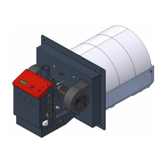
- Page 10 PV700a / PV1000a pellet burners 10/ 59 Figure 2 Main components DK9401B1 www.pelltech.eu...
- Page 11 PV700a / PV1000a pellet burners 11/ 59 Table 2 List of main components Name Description Burning The part of the burner that is inside the boiler and where pellets are burnt. chamber Burner body The part of the burner that is outside the boiler and where burner’s control and pellets supply takes place.
-
Page 12: Safety Devices
The back-burning is the biggest danger risk at burners working procedure. Back-burning appears when usual pressure or draught conditions have changed in boiler’s combustion chamber. There are several reasons for such changes. In order to secure operational and fire safety the PV700a/PV1000a burners are equipped with following safety devices: ... -
Page 13: Pellets
PV700a / PV1000a pellet burners 13/ 59 Fire safety water pressure control switch (pressostat). Enables to keep necessary water pressure in water reservoir and to ensure with that successful extinguishing procedure when needed. Pressostat switch allows starting the burner only if water supply is present and pressure exists. - Page 14 PV700a / PV1000a pellet burners 14/ 59 The boiler room where the burner is installed must fulfill all rules and recommendations given by local authorities. Boiler room must provide constant air supply of 1500 m³ per hour (ca. 1600 cm air inlet opening).
-
Page 15: Burner Installation
PV700a / PV1000a pellet burners 15/ 59 Boiler’s firebox depth L must be at least 2,5 times longer than the length of burner’s burning chamber. Thus minimal length of the firebox L for PV700 has to be 1500 mm and for PV1000 1800mm. The height of firebox must leave at least 100 mm space (H1) for ash below burning chamber. - Page 16 PV700a / PV1000a pellet burners 16/ 59 Use 6 M12x60mm bolts, spacers and distance nuts respective to the bolts. Figure 8 Install the insulation rope between the burning chamber and the boiler door. The rope must be installed near the outer perimeter of the burning chambers back wall.
- Page 17 PV700a / PV1000a pellet burners 17/ 59 Grate holders installation Install the burning chambers bottom panel (15x15mm insulation rope must be inserted to the slot in the panel) with 6 M8x16mm bolts. Install the burning chambers front panel (heat shield), use M8x16mm bolts.
- Page 18 PV700a / PV1000a pellet burners 18/ 59 Connect the moving grate holders with M6x12mm bolts. Figure 12 Install the burning chamber’s front brick holders, use M8x16mm bolts. Figure 13 DK9401B1 www.pelltech.eu...
- Page 19 PV700a / PV1000a pellet burners 19/ 59 Release the igniter tube screws and while inside the holders pull the tubes out about half of the total length. Figure 14 Move the air separator to its correct position (according to the boiler door thickness) and fix it with screws.
- Page 20 PV700a / PV1000a pellet burners 20/ 59 Install the ceramic sealing strips on the boiler door. Fix them temporarily in position with any ordinary cellophane tape (scotch). Cut away the excessive sealing on the perimeter of the air chamber. Figure 16 Mount the burner’s housing on the...
- Page 21 PV700a / PV1000a pellet burners 21/ 59 Connect the linear motor with the moving grate holder. Use 27x2,5mm pipe (length 240mm), M8x45mm bolt for the burning chamber side and a M6x25 socket set screw (DIN914 45H) on the linear motor side.
- Page 22 PV700a / PV1000a pellet burners 22/ 59 Install the 2 lower position grates . Install the 8 middle position grates with 5mm holes . Install the 8 higher position grates with 7mm holes. Figure 21 Install the ceramic seal on the back wall of the burning chamber.
- Page 23 PV700a / PV1000a pellet burners 23/ 59 Install the upper grate holder and 2 upper grates. Fix the holder with M10 wing nuts. Figure 23 Install the 6 side bricks. Install the 6 arc-stones. Notice! The arc-stones are numbered; they must be installed as pairs!
-
Page 24: Water Sprinkler
PV700a / PV1000a pellet burners 24/ 59 2.3 Water sprinkler Principal chart of water sprinkler installation is depicted in Figure 25. Water sprinkler is main safety element against back-burning. It is strongly recommended to install sprinkler system. Pressure switch allows starting the burner only if water supply is present. -
Page 25: Pellet Storage
PV700a / PV1000a pellet burners 25/ 59 20cm >60cm >65 max45 Figure 26 External auger installation 2.5 Pellet storage Pellets must be stored in a dry and ventilated room that is separated from the boiler room. A tailor made storage (silo) is recommended. All safety regulation must be taken into consideration according to the local laws. - Page 26 PV700a / PV1000a pellet burners 26/ 59 Table 4 PV1000a connectors Name Voltage, amps X11 Control voltage, boiler’s 230VAC, 3A thermostat X12 Main power supply 3x380VAC 20A X13 Safety circuit 230V X14 External auger 1 3x380V 0,55kW 1,6A X15 External auger 2...
-
Page 27: Initial Start-Up
3.1 GSM modem PV700a and PV1000a burners are ready to send burner’s error SMS messages up to 5 phone numbers. When error occurs the modem will send list with history of errors and statuses before error. If list is very long then so much information what has a room in message will be sent. -
Page 28: Error Output
PV700a / PV1000a pellet burners 28/ 59 To insert the SIM card, the modem has to be disconnected from supply mains. To insert the card push it into a slot as long as its spring clicks and fixes the card. See Figure 30. To remove card push it in as long as spring clicks and pushes it out. -
Page 29: Flue Gas Fan
PV700a / PV1000a pellet burners 29/ 59 3.3 Flue gas fan The burner needs stable under-pressure in burning chamber for its correct operation. Simplest way to assure this is to use the flue gas fan between boiler and chimney. With flue gas fan the burner can control and hold constant under-pressure. -
Page 30: Oxygen Amount Sensor
PV700a / PV1000a pellet burners 30/ 59 3.4 Oxygen amount sensor Oxygen amount sensor (oxygen sensor) allows the burner to keep pre-set oxygen level in flue gas, what increases the efficiency of the burning process. The oxygen sensor is connected to socket X23 as shown Figure If the sensor requires heater connection, it can be connected between T6 and B5. -
Page 31: Ash Removal System
PV700a / PV1000a pellet burners 31/ 59 3.5 Ash removal system The burner can control external ash removal auger and scraper motors via X25 connector. During burner’s cleaning cycle the X25 connector is powered and ash removal and scraper motors can be switched on via X25 connector’s L1 and L2. -
Page 32: Operation And Service
PV700a / PV1000a pellet burners 32/ 59 4 Operation and service 4.1 User interface The burner is controlled via user interface on the front panel. 3 row LCD screen (1) displays main menu, submenus, event log and statuses. Yellow light (2) shows the existence of flame in burning chamber. If it blinks, the burner is out of normal operation. -
Page 33: Starting And Stopping
4.4 Statuses and parameters PV700a/PV1000a pellet burner operates in many different states, which are called “Statuses” and which are displayed in user interface in STATUS menu (chapter 4.1). Burner changes its statuses based on input signals from sensors and user setup. The working statuses of the burner in typical order of succession are given in Table 9. - Page 34 PV700a / PV1000a pellet burners 34/ 59 Table 9 Summary of burner statuses Status Short description WAITING Waiting when boiler’s thermostat switches on. TESTING Boiler’s thermostat is switched on, testing the battery, fans, feeder, level sensors and draught in progress.
- Page 35 PV700a / PV1000a pellet burners 35/ 59 Table 11 CLEANING parameters PAR name PAR No Value Unit Test conditions CLEANING CYCLE PAR48 0...250 BURNING time between two CLEANING cycles. If set to 0 then CLEANING is turned off. If BURNING has been longer than 2x PAR48 set, then extraordinary cleaning will made.
- Page 36 PV700a / PV1000a pellet burners 36/ 59 At IGNITING cycle the igniter is heated up and fan blows hot air on pellets in burning chamber. Hot air ignites pellets. Igniter is working periodically at ignition time in order to avoid its overheating.
- Page 37 PV700a / PV1000a pellet burners 37/ 59 Table 15 HEAT-UP parameters PAR No Parameter name Default Unit Comment value PAR70 HEAT UP TIME Initial heat up time of ceramic stones. PAR71 HEAT UP POWER 30...70 Initial heat up power of ceramic stones.
- Page 38 PV700a / PV1000a pellet burners 38/ 59 Power level can be selected in main menu. Power level selection for Selected power burning time can be automatic or fixed on some main level. When power level is fixed, the power is...
- Page 39 PV700a / PV1000a pellet burners 39/ 59 Thermostat ON Thermostat OFF Operation power Par 17 Par 18 „Burn end“ „Slow „Hold flame“ „Burning“ „Burning“ „Slow down“ down“ Status/time Figure 35 SLOW DOWN mode The purpose of HOLD FLAME mode is to avoid burner start-up procedures i.e TESTING, CLEANING, LOADING, IGNITING etc.
-
Page 40: Output Power Levels
PV700a / PV1000a pellet burners 40/ 59 occurred errors e.g. If pellets have run out and NO PELLETS is displayed the burner stops safely normal BURNING cycle. Table 18 End burn parameters PAR No Parameter name Default Unit Comment value... - Page 41 PV700a / PV1000a pellet burners 41/ 59 Table 20 Main menu Menu Menu para- Description Default Options meter ENG settings Submenu with status STATUS-> info INFO-> Burner’s info BURNER Burner’s turning ON/OFF ON/OFF HOLD FLAME Hold flame allowed ON/OFF/AUTO HEAT UP...
- Page 42 PV700a / PV1000a pellet burners 42/ 59 Δp=-0,2/-8Pa Measured under pressure value in bpoler. -0,2 is actual pressure and -8 is set-point. Controller regulates flue gas fan speed to keep this pressure. Depends also on PAR60 value. Total=10 kg Roughly the amount of pellets burnt. It is measured by counting internal feeder rotations.
-
Page 43: Regular Maintenance
PV700a / PV1000a pellet burners 43/ 59 Menu BASE AIR increases or decreases speed of fan in all power levels by same number. It is reasonable to use base air to balance different characters of particular heating systems. For example if draught is very strong, the fan can work at lower speed and thus reduce the draught. - Page 44 PV700a / PV1000a pellet burners 44/ 59 o Amount of pellets for igniting is too small. If error is frequent, increase amount of pellets PAR24. Burner is turned OFF from main menu. STOPPED o To turn burner on hold OK button down 3 seconds or change in BURNER menu OFF to ON.
-
Page 45: Burner Status Change Logic
PV700a / PV1000a pellet burners 45/ 59 availability of fresh air and improve draught. GRATE ERROR Over- current of grate movers motor has exceeded value set in PAR47 and over- current protection has applied. o Ash removing grate has jammed before reaching extreme point. Remove reason. - Page 46 PV700a / PV1000a pellet burners 46/ 59 PRE-BURN BURNING 3 pre-burn cycles each 40 sec are done and continuous flame is recognized more than 10 seconds. LOADING 2 Pre-burn cycles are done and flame is NOT recognized and load 2 is NOT done.
-
Page 47: Annex 1 Electrical Diagrams
PV700a / PV1000a pellet burners 47/ 59 7 Annex 1 Electrical diagrams Bl Black Br Brown Bu Blue Gr Green Rd Red Wh White YL Yellow Figure 36 PV700 Electrical diagramm DK9401B1 www.pelltech.eu... - Page 48 PV700a / PV1000a pellet burners 48/ 59 Bl Black Br Brown Bu Blue Gr Green Rd Red Wh White YL Yellow Figure 37 Principle diagram DK9401B1 www.pelltech.eu...
- Page 49 PV700a / PV1000a pellet burners 49/ 59 Figure 38 Principle diagram DK9401B1 www.pelltech.eu...
-
Page 50: Annex 2 - Controller Board
PV1000a pellet burner 49/ 58 8 Annex 2 – Controller board Fuse F4=6A 24VDC Power supply Fuse F10= 2A Linear motor Figure 41 Controller board BBB v2.1 DK9401B1 www.pelltech.eu... - Page 51 Open collector output, max 200mA, 30VDC X1-10 Open collector output, max 200mA, 30VDC X2-1 X2-2 +27VDC power output, fused through F3 X2-3 +27VDC power output, fused through F2 X2-4 X3-1 + Thermocouple input (fire brick temperature sensor) X3-2 - Thermocouple input (GND) DK9401B1 www.pelltech.eu...
- Page 52 DAC 0 – 10V output X8-5 +27VDC power output, fused through F5 X8-6 PT100/mA/2.56V input. JP1 & JP2 selects function X8-7 PT100/mA input, JP3 & JP4 selects function X8-8 DC input X8-9 Flame sensor input X8-10 Flame sensor input DK9401B1 www.pelltech.eu...
-
Page 53: Annex 3 Control Unit
PV1000a pellet burner 52/ 58 9 Annex 3 Control unit F20, 21, 22, 23 INV3 INV2 INV1 Figure 42 PV1000 contrtol unit DK9401B1 www.pelltech.eu... - Page 54 INV2 L1 1-pole thermo-magnetic protector switch INV1 L1 1-pole thermo-magnetic protector switch Power supply 230VAC/27,2VDC Battery’s fuse 6A Ash auger’s motor fuse 3A Ash scraper’s motor fuse0,25A Control voltage X11 fuse1 A Cooling fan’s motor fuse 1 A DK9401B1 www.pelltech.eu...
-
Page 55: Annex 4 Table Of Parameters
PV1000a pellet burner 54/ 58 10 Annex 4 Table of parameters Firmware version: bbb: 2.08 22/11/13 PV700a PV1000a PAR Name Description Unit PAR1 FAN@200(250) Fan speed at 1.power level PV700(PV1000) PAR2 FAN@300(400) Fan speed at 2.power level PV700(PV1000) PAR3 FAN@400(550) Fan speed at 3.power level PV700(PV1000) - Page 56 SMS COUNT Selecting number of phones receiving alert SMS PAR53 TEMP.TYPE Determines temperature sensor type plugged in TMP1 connector PAR54 TEMP.LEVEL Set point value for temperature sensor plugged to °C TMP1 PAR55 TEMP.HYST PAR54 maximum set point hysteresis °C DK9401B1 www.pelltech.eu...
-
Page 57: Annex 5 Table Of Languages
PAR99 BURNER TYPE Selecting model of burner. Software of wrongly selected model works incorrectly 11 Annex 5 Table of languages Language English Spanish Estonian Finnish France Germany Greece Croatian Lithuanian Latvian Dutch Portuguese Russian Slovenian Serbian Slovakian Swedish DK9401B1 www.pelltech.eu... -
Page 58: Warranty
Warranty is valid only if the bottom half of the warranty ticket is filled in and sent or brought to the office of Pelltech OÜ Sära tee 3, Peetri, Rae vald, 75312 Harjumaa ESTONIA Ph.. + 372 677 5277 www.pelletikeskus.ee... - Page 59 Street/ House …………………………………………………… Warranty is valid only if the bottom half of the warranty ticket is filled in and sent or brought to the office of Pelltech OÜ Sära tee 3, Peetri, Rae vald, 75312 Harjumaa ESTONIA Ph.. + 372 677 5277 www.pelletikeskus.ee...
Need help?
Do you have a question about the PV700a and is the answer not in the manual?
Questions and answers