Table of Contents
Advertisement
Quick Links
Advertisement
Table of Contents

Related Manuals for Pelltech PV50c


Summary of Contents for Pelltech PV50c
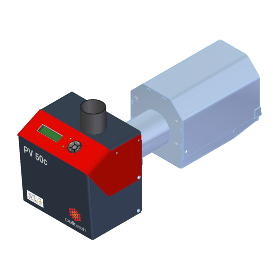
- Page 1 PV50c pellet burner User manual DK9802C2...
-
Page 2: Table Of Contents
DK9802C2 PV50c user manual ENG Vers: C2 page2/38 Table of contents Table of contents ............................. 2 General ..............................4 Unit description ..........................4 References to other documents ...................... 4 Safety ............................... 4 Safety instructions for installation, use and service ................ 5 Safety instructions regarding maintenance and cleaning ............... - Page 3 List of spare parts ..........................36 Declaration of confirmity ........................38 Warranty ............................... 39 Manufacturer of pellet burners PV50c: Pelltech OÜ Manufacturers address: Sära tee 3, Peetri, Rae vald, 75312 Harjumaa ESTONIA Name of the product: Pellet burner PV50c Ph..+3726775277 www.pelltech.eu...
-
Page 4: General
1.1 Unit description PV50c pellet burner is designed for solid fuels combustion in form of pellets. The burner operates automatically and does not require supervision. The burner is designed to work with central heating boilers for solid fuels, as well as several models of gas or oil boilers with a combustion chamber enabling the collection of ash. -
Page 5: Safety Instructions For Installation, Use And Service
DK9802C2 PV50c user manual ENG Vers: C2 page5/38 2.1 Safety instructions for installation, use and service The owner / user shall read and understand this manual before installation and operation of the burner. For proper function and to avoid accidents and damage, these instructions must be followed. Wrong handling and incorrect settings can result in injury, damage and / or malfunction of the equipment. -
Page 6: Warnings
For personal and operational safety, use only spare parts provided or approved by Pelltech OÜ in order to avoid any damage to the boiler and dangers resulting from it. Use of spare parts not provided or approved by Pelltech OÜ will void the warranty. -
Page 7: Set Of Components
PV50c burner mounted to the boiler’s door. Unique construction of PV50c allows using it in many boilers working in light oil or solid fuel or universal boilers. Unique electric ignition and automatic choosing of per-set power levels make using the pellet burner easier through the whole year. -
Page 8: Principal Function
*Not in set 4.1 Principal function The PV50c burner is meant to be installed in a boiler and fuelled with wood pellets. The burner starts always the operation by running a self test to ensure everything is working correctly. The burner is equipped with a controller which is responsible monitoring and regulating all the processes of the burner. -
Page 9: Safety Devices
Back-burning is the biggest danger risk at burners working procedure. Back-burning appears when usual pressure or draught conditions have changed in boiler’s combustion chamber. In order to secure operational and fire safety, PV50c burner is equipped with following safety devices: ... -
Page 10: Specifications
DK9802C2 PV50c user manual ENG Vers: C2 page10/38 4.3 Specifications Figure 3 Burners main measurements Table 1 Burner’s main measurements Description Unit Value total length burner housing length burning chamber´s length burning chamber´s width ⌀D1 burning chamber´s neck diameter ⌀D2... - Page 11 DK9802C2 PV50c user manual ENG Vers: C2 page11/38 Figure 4 Main components of burner Table 2 Main components list No Name Description 1 Burning chamber Place where pellets are burnt. Burning grates are made of cast iron. 2 Burner housing Part of the burner that is located outside the boiler.
-
Page 12: Pellets
Pelletized biomass is a high density, low moisture product with a high heating value that burns cleanly, consistently and efficiently. Only wood pellets according to EN 14961-2 (ENplus-A1, ENplus-A2, EN-B) can be used in PV50c burners. Table 3 Wood pellets key data... -
Page 13: Requirements
DK9802C2 PV50c user manual ENG Vers: C2 page13/38 Pellet material: Pellets should be made of softwood or hardwood or some combination of the two. Pellets should smell like wood. If not, then other materials may have been used in their manufacturing process. - Page 14 DK9802C2 PV50c user manual ENG Vers: C2 page14/38 Double hinges Figure 5 Critical point Figure 6 Boiler firebox requirements Model PV50c Min. furnace total length – L Min. furnace diameter – H Min. distance under the burning chamber – H1...
-
Page 15: Installation Of The Burner To The Boiler
Figure 8 Brackets to move There is no need to remove grates when connecting PV50c burner with its burning chamber. Grates and grate lever may stay on their places. They are connected to burners housing via fast joint. If there is need to remove grates anyway, e.g. -
Page 16: External Auger
DK9802C2 PV50c user manual ENG Vers: C2 page16/38 6. Make sure that the end of burners feeder auger tube and rear wall of the burning chamber were in one level and brackets (1) would enter freely to its nests. If not so, turn the power screw of linear motor clockwise and try again. -
Page 17: Electrical Connections
DK9802C2 PV50c user manual ENG Vers: C2 page17/38 40-70 cm 10 .. 20 cm Figure 12 External auger installation 6.2 Electrical connections The burner is equipped with a standard oil burner plug that has 7 contacts. There are different connection schemes used for different boilers. -
Page 18: Initial Start Up
DK9802C2 PV50c user manual ENG Vers: C2 page18/38 6.3 Initial start up Before starting the burner for the first time up, make sure that: Burner housing and burning chamber are securely connected by brackets. The neck of burning chamber sits correctly in burner’s housing. -
Page 19: Starting And Stopping
DK9802C2 PV50c user manual ENG Vers: C2 page19/38 Table 5 User interface control buttons Button Pressing the button time Action Less than 3 seconds Entering into sub-menu Confirming setting (when blinks) More than 3 sec Resetting error status and turning burner ON... - Page 20 DK9802C2 PV50c user manual ENG Vers: C2 page20/38 Table 6 Burner status description Status Description message STOPPED The burner is turned off from main menu. WAITING Burner is turned on and waits for boiler’s thermostat to switch on. There are no time limit for WAITING status.
-
Page 21: Output Power Levels
DK9802C2 PV50c user manual ENG Vers: C2 page21/38 HOLD HOLD FLAME mode purpose is to avoid burner start-up procedures when BURNING cycle is FLAME much longer than WAITING status. In HOLD FLAME mode, minimum fuel and air amount is delivered into burning chamber. HOLD FLAME mode can be switched from burner main menu to ON, OFF or AUTO. - Page 22 DK9802C2 PV50c user manual ENG Vers: C2 page22/38 Table 7 Main menu Menu Sub menu Description Default Options settings STATUS-> Submenu with status and error info INFO-> Burner’s technical info BURNER Turning burner ON/OFF ON/OFF HOLD FLAME Hold flame activated...
-
Page 23: Regular Maintenance
PV20…PV500”. 7.7 Regular maintenance Pellet burner PV50c needs regular maintenance. The frequency of it depends on quality of pellets and intensity of heating. Average frequency is once a month or after every 2 months. Despite burner has ash removing system, the ash collects under and on the grates. -
Page 24: Replacing The Components
DK9802C2 PV50c user manual ENG Vers: C2 page24/38 6. Remove ash from down side of grates. 7. Place back all removed parts as they were. 8. To end the cleaning shut the boilers door and turn thermostat to required temperature and turn burner ON. -
Page 25: Replacing The Igniter
DK9802C2 PV50c user manual ENG Vers: C2 page25/38 In order to remove burner’s upper cover, firstly open burner’s lower cover. Then remove upper cover's screws (3) 2 pcs. Pull the cover upwards. Notice! It might be necessary to remove user interface buttons from the controller board to complete removing upper cover from the burner. -
Page 26: Replacing Fuses
DK9802C2 PV50c user manual ENG Vers: C2 page26/38 Figure 19 Safety thermostat 8.3 Replacing fuses Burner’s controller is protected against the errors of external devices with electrical fuses. Fuses may burn out in case a foreign object gets into the fan or motor and blocks their work. Fuses are located in the controller’s plate and are labelled as F1...F11. -
Page 27: Replacing Flame Sensor
DK9802C2 PV50c user manual ENG Vers: C2 page27/38 8.5 Replacing flame sensor Flame sensor may get dirty or melt in case of back burning. Flame sensor consists of light sensitive resistor and transparent plastic housing. Housing is situated inside of black rubber nest. For replacement small screwdriver is needed. -
Page 28: Replacing Battery
DK9802C2 PV50c user manual ENG Vers: C2 page28/38 Remove 4 tin screws and fan’s lower screw Figure 20 Removing the screws 8.7 Replacing battery Battery has to be replaced when burner displays permanently E48BATTERY. As battery is safety element the burner checks permanently its running order and doesn’t start next working cycle when battery’s voltage is lower than 11V. -
Page 29: State Change Logic
DK9802C2 PV50c user manual ENG Vers: C2 page29/38 CAUTION! ALLWAYS CONNECT RED WIRE WITH RED BATTERY CONTACT (+) AND BLACK WIRE WITH BLACK BATTERY CONTACT (-). WRONG CONNECTION WILL DAMAGE THE CONTROLLER AND MAY BE DANGER TO PEOPLE NEARBY. 9 State change logic... - Page 30 DK9802C2 PV50c user manual ENG Vers: C2 page30/38 LOADING 2 IGNITION time reached and flame not recognized, LOADING 2 hasn’t been done. IGNITION PRE-BURN Flame recognized. E24 IGNITION IGNITION time reached and flame not recognized, LOADING 2 has been done.
-
Page 31: Error Messages And Solutions
DK9802C2 PV50c user manual ENG Vers: C2 page31/38 WAITING Flame is not recognized during END BLOW TIME (par27) and BURNER is set ON. END BLOW STOPPED Flame is not recognized during END BLOW TIME (par27) and BURNER is set OFF. -
Page 32: Annex 1. Electrical Diagram
DK9802C2 PV50c user manual ENG Vers: C2 page32/38 14 Annex 1. Electrical diagram Figure 22 Electrical diagram... -
Page 33: Annex 2. Screw Connectors
DK9802C2 PV50c user manual ENG Vers: C2 page33/38 15 Annex 2. Screw connectors 230 VAC devices X1-1 Igniter X1-2 Igniter X1-3 Err relay output X1-4 External auger N X1-5 External auger L X1-6 Mains supply L X1-7 Flue gas fan L X1-8 Boiler’s thermostat... -
Page 34: Annex 3. Controller Board Ep0001B3
DK9802C2 PV50c user manual ENG Vers: C2 page34/38 16 Annex 3. Controller board EP0001B3 Figure 23 Controller EP0001B3... -
Page 35: Annex 4. Controller's Connectors
DK9802C2 PV50c user manual ENG Vers: C2 page35/38 17 Annex 4. Controller’s connectors MODBUS Modbus interface MODBUS-1 +5V output, unfused MODBUS-2 Signal A MODBUS-3 Signal B MODBUS-4 Ground FANx Primary and secondary air fans FANx-1 Fan power, PWM 5A cont / 25A 100ms... -
Page 36: Annex 5. List Of Languages
DK9802C2 PV50c user manual ENG Vers: C2 page36/38 18 Annex 5. List of languages Table 9 List of languages Language English Spanish Estonian Finnish France Germany Greece Croatian Lithuanian Latvian Dutch Portuguese Russian Slovenian Serbian Slovakian Swedish 19 List of spare parts... - Page 37 Product Description code MF0002 Fan for PV50bc ET0001 Power supply for PV50c EU0008 Connector 7 pin (female) EA0001 Battery 12 V, 1,2 Ah for PV20/30/50/100/180 MM0002 Linear motor for PV50bc AL0002 Photo cell with rubber case for PV20/30/50 (cable 15 cm)
-
Page 38: Declaration Of Confirmity
20 Declaration of confirmity... -
Page 39: Warranty
Warranty Warranty objects in this context are pellet burner PV50c, external augers PA15XX or PA 20XX. Producer gives 2 years warranty from the date of sales for the PV50c burners and PA15XX and PA20XX augers. Warranty is valid only in country where the burner is bought from. - Page 40 …………………………………………………… Street/ House …………………………………………………… Warranty is valid only if the bottom half of the warranty ticket is filled in and sent or brought to the office of Pelltech OÜ Sära tee 3, Peetri, Rae vald, 75312 Harjumaa ESTONIA Ph..+3726775277 www.pelltech.eu...
Need help?
Do you have a question about the PV50c and is the answer not in the manual?
Questions and answers