Table of Contents
Advertisement
Quick Links
UCL Installation Guide
Index
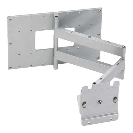
Mounting the Wall Plate
Mounting to Wooden Stud
Mounting the Cantilever Assembly
Adjusting the Display
180° Pan
Mounting the Wall Plate
Mounting to Wooden Stud
1. Determine the location where you want the display mounted on the
wall.
2. Use stud finder to locate and mark the center of the two studs.
3. Remove Plasma CL from box. Remove UM-1 Adaptor plate from the
Mounting Head, and set the four 3/8"-16 button head cap screws aside
for later.
Note that the cantilever arm is mounted at the end of the wall plate for
shipping.
4. Remove cantilever arm from Wall plate.
5. Align center mounting holes of wall plate with center marks on studs.
Using the wall plate as a template, mark the mounting holes and center
J box hole. Install J box as required.
Note: Electrical outlets should only be installed by a qualified
electrician.
1
Advertisement
Table of Contents

Subscribe to Our Youtube Channel
Related Manuals for Omnimount UCL


Summary of Contents for Omnimount UCL
- Page 1 UCL Installation Guide Index Mounting the Wall Plate Mounting to Wooden Stud Mounting to Masonry Mounting the Cantilever Assembly Configuring the UM-1 Adaptor Plate Mounting the Display Adjusting the Display Roll Control Vertical Tilt Swivel 180° Pan Stowing the Screen...
- Page 2 6. Drill mounting holes with 9/32” bit. Mounting holes should be 3” (76 mm) deep. Mounting to Masonry 1. Using the wall plate as a template, mark the mounting holes in the desired mounting location. 2. Drill mounting holes with 3/8” (10mm) masonry bit. Mounting holes should be a minimum of 2 9/16”...
- Page 3 Configuring the UM-1 adaptor plate Measure display The UM-1 ships with a standard set of mounting rails pre-installed. These rails will fit a display where the vertical distance between mounting lands on the display are 17 1/8” or less. If your display is larger than this, you will need to install the large set of mounting rails, which are included with the UM-1.
- Page 4 Mount UM1 to Display Hardware Selection a. Consult the supplied Hardware Cross Reference List. b. Select the mounting hardware for your display. Attach UM-1 to Display a. Position the UM-1 over back of display. b. Thread mounting screws through square washers and spacers (if required), as shown.
- Page 5 4. Attach selected side rails to sliders as shown. 5. Re-install slider assemblies into channels as shown, and return to Set UM-1 Width section. Mounting the Display 1. Locate the set of four 3/8”-16 button head cap screws removed at the beginning of the installation.
- Page 6 Display Adjustments Roll Control Function - Horizontal leveling of the display. Operation - Grasp the sides of the display, and roll it into the desired position. Adjusting Roll Tension – Roll tension is controlled by the two tension bolts located on the outer edges of the nose piece. Use an open-ended 9/16”...
- Page 7 180° Pan Purpose – Allows display to be positioned perpendicular to wall. Operation – Extend cantilever arm completely. Fully swivel display in desired direction. Note: Maximum screen size for full 180° Pan is approximately 50”. Stowing the Screen Purpose – Allows display to be folded flat to the wall. Operation –...
Need help?
Do you have a question about the UCL and is the answer not in the manual?
Questions and answers