Table of Contents
Advertisement
Quick Links
Instruction manual
VWR
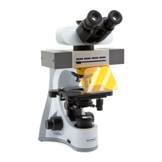
Microscope VisiScope
®
Series 534
Model
TL534B FL BG
TL534B FL4
TL534B-SA FL4
VisiCube TL_B
VisiCube TL_G
VisiCube TL_V
VisiCube TL_UV
VisiCube TL_R1
VisiCube TL_R2
VisiCube TL_R3
VisiCube TL_FR
VisiCube TL_A
VERSION: 1.0
ISSUED: 01/02/2021
European Catalogue Number
630-3270
630-3243
630-3244
630-3245
630-3246
630-3247
630-3248
630-3249
630-3250
630-3251
630-3252
630-3253
Advertisement
Table of Contents

Subscribe to Our Youtube Channel
Related Manuals for VWR VisiScope 534 Series


Summary of Contents for VWR VisiScope 534 Series
- Page 1 Instruction manual Microscope VisiScope ® Series 534 Model European Catalogue Number TL534B FL BG 630-3270 TL534B FL4 630-3243 TL534B-SA FL4 630-3244 VisiCube TL_B 630-3245 VisiCube TL_G 630-3246 VisiCube TL_V 630-3247 VisiCube TL_UV 630-3248 VisiCube TL_R1 630-3249 VisiCube TL_R2 630-3250 VisiCube TL_R3 630-3251 VisiCube TL_FR 630-3252...
- Page 2 MANUFACTURED FOR: Europe VWR International bv Researchpark Haasrode 2020 Geldenaaksebaan 464 B-3001 Leuven + 32 16 385011 be.vwr.com UK Importer VWR International Ltd Hunter Boulevard, Magna Park Lutterworth, Leicestershire, LE17 4XN uk.vwr.com Country of Origin Italy vwr.com | Instruction manual...
-
Page 3: Table Of Contents
11.3 Use of light excluding plate 11.4 Use of UV shield Microphotography 12.1 Use of C-mount cameras 12.2 Use of reflex cameras Troubleshooting Repair and maintenance Technical service Warranty Compliance with local laws and regulations Disposal Instruction manual | vwr.com... -
Page 4: Warning
The following chart is an illustrated glossary of the symbols that are used in this manual. CAUTION This symbol indicates a potential risk and alerts you to proceed with caution ELECTRICAL SHOCK This symbol indicates a risk of electrical shock. vwr.com | Instruction manual... -
Page 5: Instrument Description
RING OBSERVATION HEAD NOSE PIECE SLIDE HOLDER CONDENSER HEIGHT ADJUSTMENT KNOB CONDENSER COARSE UPPER LIMIT KNOB FINE FOCUS KNOB CONDENSER CENTERING SCREWS COARSE MAIN SWITCH / FOCUS TRANSMITTED LIGHT KNOB ADJUSTMENT KNOB Instruction manual | vwr.com vwr.com | Instruction manual... - Page 6 Opposite side LIGHT PATH SELECTOR LEVER REFLECTED LIGHT ADJUSTMENT KNOB FLUORESCENCE CUBE SELECTOR LEVER UV SHIELD OBJECTIVES STAGE APERTURE DIAPHRAGM X/Y MOVEMENT KNOBS FIELD DIAPHRAGM TENSION ADJUSTMENT RING vwr.com | Instruction manual...
-
Page 7: Unpacking
Power supply ‒ TL534B FL BG / TL534B FL: W-PLAN series ‒ TL534B-SA FL4: W-PLAN F series ‒ 6V for transmitted light Observation head ‒ 12V for fluorescence Epi-illuminator Light excluding plate Allen wrench UV protection shield Instruction manual | vwr.com... -
Page 8: Microscope Assembling
Insert both eyepieces into the tubes of the optical head. (Fig. 4) Condenser is pre-installed in the factory. To remove the condenser use an Allen wrench 1,5 mm diam and operate on the locking screw placed on the right side of the condenser holder. FIGURE 4 vwr.com | Instruction manual... -
Page 9: Installing Fluorescence Filter
FIGURE 7 Open the top door of the fluorescence illuminator by unscrewing the four screws (2) and release the cover. (Fig. 8) FIGURE 8 Instruction manual | vwr.com... -
Page 10: Replacing Fluorescence Filter
Disconnect the plug (5) related to the cube you want to replace. (Fig. 11) Remove the fluorescence cube from the dovetail of the cube slider. Repeat steps 4. to 9. of paragraph 7.1.1. to install a new fluorescence cube. FIGURE 12 vwr.com | Instruction manual... -
Page 11: Polarizing Set (Optional)
Loosen the head fixing knob (2) and remove the head from the microscope frame. (Fig. 14) FIGURE 14 Insert the analyzer into the hole inside the frame (3). (Fig. 15) Put back the head into its original position and lock the fixing knob. FIGURE 15 Instruction manual | vwr.com... -
Page 12: Brightfield Observation Procedures (Transmitted Light)
Condenser centering Aperture diaphragm Adjust aperture and field diaphragms Field diaphragm Nosepiece Insert in the light path the desired objective and focus the spec- imen Coarse and fine focusing knobs Adjust brightness Light adjustment dial Begin observation vwr.com | Instruction manual... -
Page 13: Use Of The Microscope (Transmitted Light)
Open the spring arm of the slide holder (4) and place frontally the slides on the stage. (Fig. 19) Gently release the spring arm of the slide holder. A sudden release of the spring arm could cause the falling of the slide. FIGURE 19 Instruction manual | vwr.com... -
Page 14: Diopter Adjustment
(Fig. 22) Position Light 100% Eyepieces 100% Tv FIGURE 22 9.8 Use of eye shields Use with eyeglasses Fold rubber eyeshields with both hands. Folded eyeshields avoid scratching the lenses of eyeglasses. (Fig. 23) FIGURE 23 vwr.com | Instruction manual... -
Page 15: Centering The Condenser
28. Example: with objective PLAN 40x/0,65 set the scale to 0.65 x 0.8 = 0,52 FIGURE 27 Instruction manual | vwr.com... -
Page 16: Use Of Oil Immersion Objective
Remove the specimen from the stage. Looking inside the eyepieces, rotate the polarizer until the darkest position is achieved. Once the dark is achieved (“extinction” or “Crossed Nicol” position) it is possible to begin the observation. vwr.com | Instruction manual... -
Page 17: Fluorescence Observation Procedures (Reflected Light)
Fluorescence filter turret Insert in the light path the filter suitable for the specimen Nosepiece Insert desired objective for the observation and focus the specimen Coarse and fine focusing knobs Adjust light intensity Fluorescence main switch Begin observation Instruction manual | vwr.com... -
Page 18: Use Of The Microscope (Reflected Light)
655 nm 665-715 nm ‒ AlexaFluor 647 ‒ Draq5 VisiCube TL_fr 623-678 nm 685 nm 690-750 nm ‒ Cy5.5 VisiCube TL_a 720-760 nm 770 nm 780LP nm ‒ Li_Cor IR dye 800 vwr.com | Instruction manual... -
Page 19: Use Of Light Excluding Plate
UV rays coming from the fluorescence light source. Loosen the two locking screws (1). (Fig. 34) FIGURE 34 Insert the grooves of the UV shield (2) into the holes (Fig. 35) and tighten the screws (1) again. FIGURE 35 Instruction manual | vwr.com... -
Page 20: Microphotography
To calculate the magnification of the camera: objective magnification * camera magnification * lens magnification. If using an SLR camera, mirror movement may cause the camera to vibrate. We suggest lifting the mirror, using long exposure times and a remote cord. vwr.com | Instruction manual... -
Page 21: Troubleshooting
To a certain extent it is due to achromatic objectives features proper position Stray light entering in the microscope through eyepieces or Bright spots appear on the image Cover eyepieces and viewfinder with a dark cloth camera viewfinder Instruction manual | vwr.com... -
Page 22: Repair And Maintenance
Product in its local environment. VWR will not be held liable for any related omission or for not And as a final option use the piece of cloth moistened with a 3:7 obtaining the required approval or authorization, unless any mixture of ethanol and ether. -
Page 23: Disposal
By doing so, you will help to conserve natural and environmental resources and you will ensure that your equipment is recycled in a manner that protects human health. Thank you Instruction manual | vwr.com 23... - Page 24 (international) info.no@vwr.com Leicestershire info.fr@vwr.com LE17 4XN + prix appel Tel.: +44 (0) 800 22 33 44 * 0,18 € TTC/min uksales@vwr.com GO TO VWR.COM FOR THE LATEST NEWS, SPECIAL OFFERS AND DETAILS FROM YOUR LOCAL VWR SUPPORT TEAM ZPROVWRI31790-EN ©2021...
Need help?
Do you have a question about the VisiScope 534 Series and is the answer not in the manual?
Questions and answers