Table of Contents
Advertisement
Quick Links
www.sigineer.com
Transformer Based Off Grid
Stackable Solar Inverter Charger with AC
Coupling
User's Manual
For Model:
MS6048D
Version 2.1 (PN:MS604820220608)
Manufacturer Information
Sigineer Power Limited
Email: info@sigineer.com
TEL: +86 769 82817616
US Warehouse: 4415 S 32nd St, Phoenix, AZ 85040
1
Advertisement
Table of Contents

Subscribe to Our Youtube Channel
Related Manuals for Sigineer Power MS6048D


Summary of Contents for Sigineer Power MS6048D
- Page 1 Transformer Based Off Grid Stackable Solar Inverter Charger with AC Coupling User’s Manual For Model: MS6048D Version 2.1 (PN:MS604820220608) Manufacturer Information Sigineer Power Limited Email: info@sigineer.com TEL: +86 769 82817616 US Warehouse: 4415 S 32nd St, Phoenix, AZ 85040...
-
Page 2: Table Of Contents
Appendix 1 : MS6048D Solar Inverter Spec Sheet ......................... 44 Please record the Sigineer Power unit’s model and serial number in case you need to provide this information in the future. It is much easier to record this information now than try to gather it after the unit has been installed. -
Page 3: Important Safety Information
www.sigineer.com 1 Important Safety Information Save This Manual! Read this manual before installation, it contains important safety, installation and operating instructions. Keep it in a safe place for future reference. All wiring must follow the National Electric Code, Provincial or other codes in effect at the time of installation, regardless of suggestions in this manual. -
Page 4: Precautions When Working With Batteries
2.1 General Information Thank you for purchasing the MS6048D Off Grid Solar Inverter/Chargers. The MS6048D transformer based Off Grid Solar Inverter/Charger is a combination of 4 products: 1. Transformer based DC to AC power inverter 2. AC to DC utility battery charger 3. -
Page 5: Mechanical Design
& amperage, DC/AC transfer conditions, etc. The MS6048D model is built with 48V DC input and output pure sine wave split phase output. You can get 36KW split phase by stacking them up to 6 pcs. - Page 6 www.sigineer.com...
-
Page 7: Features
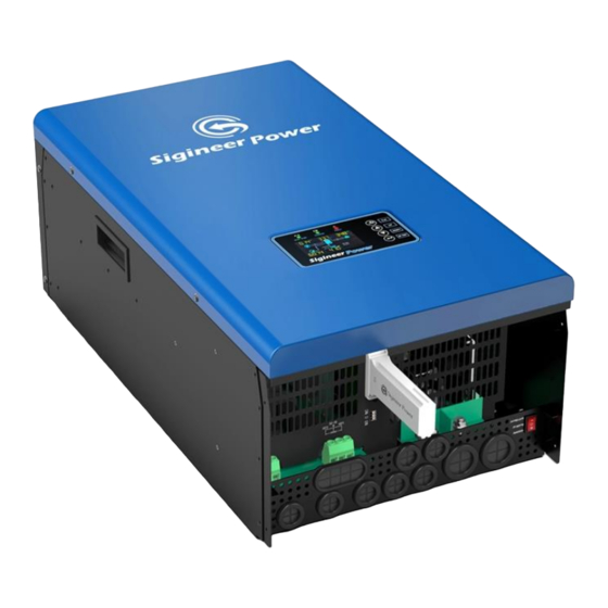
www.sigineer.com 1.LCD Display 2.Status Indicator 3.Charging Indicator 4.Fault Indicator 5. Function Buttons 6. RS485 Communication Port (For Expansion) 7. BMS Communication Port(For 8. PV Input Terminal 9. Parallel Communication Ports RS485/CAN Protocol) 10. Current Sharing Ports 11 AC Output 12. AC Input Terminal 13. -
Page 8: Electrical Performance
2.4.1 DC to AC Invert Overload Capacity The MS6048D inverter/charger has different overload capacities, making it ideal to handle demanding loads. 1 For 110%<Load<150%, Fault (Power off) after 10 seconds. 2 For 150%<Load≤200%, Fault (Power off) after the 5 seconds. - Page 9 www.sigineer.com Software timer will measure the time from charger start until the battery charger reaches 0.3V below the boost voltage, then take this time as T0 and T0× 10 = T1. Absorb Charging: This is the second charging stage and begins after the absorb voltage has been reached. Absorb Charging provides the batteries with a constant voltage and reduces the DC charging current in order to maintain the absorb voltage setting.
- Page 10 AC Charging Current MPPT Solar Charger Max Charging Current MS6048D The MPPT Solar Charger will automatically work when the inverter is powered off. Even when the power switch is in unit off position, the built-in solar charger will automatically work when PV input voltage and battery voltage is qualified, this is to optimize solar production for battery charging.
-
Page 11: Dc&Ac Transfer
www.sigineer.com 2.4.3 DC&AC Transfer While in the Standby Mode, the AC input of the inverter is continually monitored. Whenever AC power falls out of the trip voltages, the inverter automatically transfers back to the Invert Mode with minimum interruption to your appliances. The transfer from AC mode to Inverter mode occurs in approximately 10 milliseconds, with the worst case of 20 milliseconds. -
Page 12: Protections
www.sigineer.com Note: The minimum power of a load to take inverter out of sleep mode (Power Saver On) is 100 Watts. When the inverter is in idle, even there is AC input power, the inverter will discharge the battery as the LCD, relay, fans are powered by DC. -
Page 13: Lcd & Specification Setup
www.sigineer.com same protocol. To monitor the inverter on a computer, please download the software (SG Solar Power Monitor) from our website in the Support>Software Download section. The V Series inverters can be remotely monitored by a Wi-Fi or GPRS module plugged into its USB port. The Wi-Fi / GPRS module is a plug-and-play monitoring device which allows users to monitor the status of the PV system from a mobile phone APP or from the website anytime anywhere. - Page 14 www.sigineer.com mode or to enter setting mode Icon Description AC Input Information AC input icon Indicate AC input power, AC input voltage, AC input frequency, AC input current Indicate AC power loads in bypass PV Input Information PV input icon Indicate PV power, PV voltage, PV current, etc Output Information Inverter icon...
- Page 15 www.sigineer.com In AC mode, battery icon will present Battery Charging Status Status Battery voltage LCD Display <48V 4 bars will flash in turns. Constant Current mode / 48 ~ 50V Bottom bar will be on and the other three bars will Constant Voltage mode flash in turns.
- Page 16 If solar energy is not sufficient to power all connected loads, solar and utility will power loads at the same time. Battery provides power to the loads only when solar energy is not sufficient and there is no utility. Program 02: Maximum Charging Current MS6048D model: default 60A, 10A~100A Settable...
- Page 17 2 voltages below the lower value in program 19 and 20. Program 03: AC Input Voltage Range 03 APL: Appliance Mode In Appliance Mode, the acceptable AC input voltage range is MS6048D 90~280VAC± 7V. 03:UPS In UPS Mode, the acceptable AC input voltage range: MS6048D 170~280VAC±...
- Page 18 Program 07: Automatic OverTemp Restart Program 08: AC Output Voltage The AC output voltage between hot and neutral can be set to 208V, 220V, 230V and 240V for MS6048D. Program 09: AC Output Frequency The AC Output Frequency can be set to 50Hz or 60Hz.
- Page 19 The setting works when program 01 is in “SBU Priority” or “Solar Priority” Mode. Model # Default Value Resettable Range MS6048D 46V/50% 44V~51.2V/6%-95% The battery SOC will be displayed when BMS communication is established. Program 13 AC to DC Transfer Voltage The setting works when program 01 is in “SBU Priority”...
- Page 20 Model # Default Value Resettable Range MS6048D 56.4V 48V~58.4V If user-defined setting (USE/US2) is selected in program 5, this program can be set up. When the battery is charged to CV setting, the voltage must drop by 2 volts to activate the charger.
- Page 21 Program 28 Address setting Default 001. 001-255. Settable. It is for external solar charger expansion. Program 36 Lithium BMS Protocol For Sigineer Power LFP power walls, the protocol is L01. Please refer to “05: LI” for details. Program 37 Real time setting---Year...
- Page 22 www.sigineer.com Allow utility to charge the battery all day run. 0000(default) The timer allows utility to charge the battery at preset time. Use 4 digits to represent the time period, the upper two digits represent the time when utility start to charge the battery, setting range from 00 to 23, and the lower two digits represent the time when utility end to charge the battery, setting range from 00 to 23.
- Page 23 www.sigineer.com 05 Battery Type AGM Battery (Default) 05 Battery Type Flood Battery 05 Battery Type User-Defined 05 Battery Type User-Defined 2 05 Battery Type Lithium 06 Automatic Overload Restart Restart Disable (Default) 06 Automatic Overload Restart Restart Enable 07 Automatic OverTemp Restart Disable (Default) Restart 07 Automatic OverTemp...
- Page 24 www.sigineer.com 16 Backlight On/Off Control Backlight off 17 Beeps once between AC Alarm on (default) and DC Transfer 17 Beeps once between AC Alarm off and DC Transfer 18 Overload Bypass Bypass Disable (default) 18 Overload Bypass Bypass enable 19 C.V. Charging Voltage 48V model: default 56.4V, 48.0V~58.4V Settable...
- Page 25 www.sigineer.com 43 Battery Equalization Enable 44 Battery Equalization Default 58.4V, 48~60V Voltage settable 45 Battery Equalization Time Setting range is from 5min to 900min. Increment of each click is 1min. 46 Battery Equalization Setting range is from Timeout 5min to 900min. Increment of each click is 1 min.
- Page 26 www.sigineer.com (Default Display Screen) ① AC Input frequency ② Output frequency ③ Load power in VA ④ PV energy sum in KWH ⑤ Battery percentage ⑥Warning or Fault code ① AC Input current ② Output current ③ Load percentage ④ PV input current ⑤...
- Page 27 www.sigineer.com Operation mode Description LCD display Standby mode / Power saving Charging by utility and PV Charging by utility mode energy. Note: *Standby mode: The inverter is not turned on yet but at this time, the inverter No output is can charge battery without supplied by the AC output.
-
Page 28: Audible Alarm
www.sigineer.com Power from battery only The inverter is built with automatic PV and utility power wakeup feature. When the power switch is in power off, and qualified PV input, the PV charger will be activated, and the rest part of the inverter will remain powered off. In this mode, the utility power can only illuminate the LCD, it can’t charge batteries. -
Page 29: Automatic Recovery Operation
When the charging current reaches the preset amperage and/or charging voltage reaches the float charging voltage, the MS6048D will increase the output frequency gradually until it reaches 63Hz. When the MS6048D reaches 63Hz, it will cause most grid tie inverters to alarm and shut off, the MS6048D inverter will solely power the loads. -
Page 30: Advanced Utility Charging & Bypass Control With Timer
www.sigineer.com 2.4.13 Advanced Utility Charging & Bypass Control With Timer The M3048BP and M5000H-48BP inverters are designed with a timer to control its AC output power and AC charger at preset time frame. This will enable the inverter to use utility power at off peak hours to save the electricity bills. 2.4.14 Automatic Neutral-to-Ground Bonding The automatic neutral-to-ground bonding feature uses an internal relay that automatically connects the AC neutral output to the vehicle/boat’s safety ground (“bonding”... -
Page 31: Installation
www.sigineer.com 3 Installation 3.1 Location Follow all the local regulations to install the inverter. Please install the equipment in a location of Dry, Clean, Cool with good ventilation. Working temperature: ‐10℃ to 55℃(14℉ to 131℉) Storage temperature: ‐15℃ to 60℃(5℉to 140℉) Relative Humidity: 5% to 95%,non-condensing Cooling: Forced air Warning! Operation in a condensing environment will invalid warranty. -
Page 32: Battery Wiring
www.sigineer.com 3.3 Battery Wiring Before connecting all wiring, please take off the DC and AC terminal cover by removing their screws. The DC terminal bolt size is M6 and the diameter of the DC cable holes on the box is 18mm. It is suggested the battery bank be kept as close as possible to the inverter. - Page 33 www.sigineer.com Battery cables must have crimped (or preferably, soldered and crimped) copper compression lugs unless aluminum mechanical lugs are used. Soldered connections alone are not acceptable. High quality, UL-listed battery cables are available .These cables are color-coded with pressure crimped, sealed ring terminals. Battery terminal must be clean to reduce the resistance between the DC terminal and cable connection.
-
Page 34: Pv Wiring
www.sigineer.com WARNING input connections will cause permanent damage to the inverter which is not covered under warranty. Always check polarity before making connections to the inverter. The inverter contains capacitors that may produce a spark when first connected to battery. Do not mount in a confined a battery or gas compartment. -
Page 35: Communication With Lithium Batteries
www.sigineer.com Suggested cable requirement for AC wires Model Gauge Torque Value M3048BP 8 AWG 1.2~ 1.6Nm M5000H-48BP 8 AWG 1.2~ 1.6Nm Please follow below steps to implement AC input/output connection: *Before making AC input/output connection, be sure to open DC protector or disconnector first. *Remove insulation sleeve 10mm for six conductors. - Page 36 www.sigineer.com Connect one end of RJ45 of battery to BMS communication port of inverter. Connect the other end of RJ45 cable to battery communication port. Lithium Battery Connection (optional) If choose lithium battery for the inverter, you are allowed to use the lithium battery which has been configured.
-
Page 37: Inverter Parallel Operation
www.sigineer.com LCD setting For Lithium Batteries To make the inverter communicate with the battery BMS, the battery type should be set to “LI” in Program Please refer to “05: LI” for details. Note: When multiple inverters are paralleled with multiple lithium batteries, please follow the below setup. 1 Out of the lithium batteries, set one unit as the master and the rest as slave as per the lithium DIP/ADS switches. -
Page 38: Lcd Setting For Parallel Operation
www.sigineer.com Four inverters in parallel: Power Wire Connection Communication Wire Connection Five inverters in parallel: Power Wire Connection Communication Wire Connection Six inverters in parallel: Power Wire Connection Communication Wire Connection 3.7.4 LCD Setting For Parallel Operation Setting Program: Please refer to program 23 Commissioning Parallel in single phase Step 1: Check the following requirements before commissioning:... - Page 39 www.sigineer.com Note: Master and slave units are randomly defined. Step 4: Switch on all AC breakers of Line wires in AC input. It’s better to have all inverters connect to utility at the same time. If not, it will display warning 15. LCD display in Master unit LCD display in Slave unit Step 5: If there is no more fault alarm, the parallel system is completely installed.
- Page 40 www.sigineer.com Step 5: If there is no more fault alarm, the system to support 3-phase equipment is completely installed. Step 6: Please switch on all breakers of Line wires in load side. This system will start to provide power to the load.
-
Page 41: Communication With Computer
www.sigineer.com Note 1: If there’s only one inverter in L1-phase, the LCD will show as “HST”. If there is more than one inverter in L1-phase, the LCD of the HOST inverter will show as “HST”, the rest of L1-phase inverters will show as “2P0”. -
Page 42: Maintenance & Troubleshooting
www.sigineer.com 4 Maintenance & Troubleshooting This troubleshooting guide contains information about how to troubleshoot possible error conditions while using the M3048BP and M5000H-48BP Solar Power Inverter/Chargers. The following chart is designed to help you quickly pinpoint the most common inverter failures. Indicator and Buzzer Fault Code Fault Event... - Page 43 www.sigineer.com CAN fault Host loss Warning Indicator Warning Code Warning Event Audible Alarm Icon flashing Fan is locked Beep 3 times every second Over temperature Beep once every second Battery is over-charged Beep once every second Low battery Beep once every second Overload Beep once every 0.5 second Output power derating...
- Page 44 www.sigineer.com Cell over voltage Beep once every second Cell under voltage Beep once every second Total over voltage Beep once every second Total under voltage Beep once every second Discharge over current Beep once every second Charge over current Beep once every second Discharge over temperature Beep once every second Charge over temperature...
- Page 45 www.sigineer.com 2.Replace the fan. continuously and red 1.Check whether the air flow of the unit is blocked or LED is on.(Fault code) Internal temperature of component Fault code 02 whether the ambient temperature is too high. is over 100℃. 2.Check whether the thermistor plug is loose. Buzzer beeps once Restart the unit, if the error happens again, please Battery is over-charged.
-
Page 46: Warranty
Appendix 1 : MS6048D Solar Inverter Spec Sheet MODEL # MS6048D... - Page 47 www.sigineer.com Battery Voltage 48 VDC Output Waveform Pure Sine Wave AC Voltage Regulation (Batt. Mode) 120/240 VAC ± 5% Surge AC Output Power 18000W Output Frequency 50Hz/60Hz(default) 90A/ 300μs Max. Output Fault Current/ Duration Max. Output Overcurrent Protection DC To AC Efficiency (Peak) 10s@101%~150% load;...
- Page 48 READ THIS MANUAL BEFORE INSTALLATION, IT CONTAINS IMPORTANT SAFETY, INSTALLATION AND OPERATING INSTRUCTIONS. KEEP IT IN A SAFE PLACE FOR FUTURE REFERENCE. Sigineer Power Limited Email: info@sigineer.com TEL: +86 769 82817616 US Warehouse: 4415 S 32nd St, Phoenix, AZ 85040...
Need help?
Do you have a question about the MS6048D and is the answer not in the manual?
Questions and answers