Table of Contents
Advertisement
www.sigineer.com
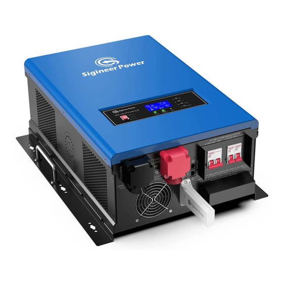
Transformer Based Off Grid
Solar Inverter Charger
User's Manual
(6KW & 12KW 48Vdc 120/240Vac Split Phase)
Version 1.3 (PN:60000-20211231)
Last edition: Dec 28th 2021
Manufacturer Information
Sigineer Power Limited
Email: info@sigineer.com / TEL: +86 769 82817616
US Warehouse: 4415 S 32nd St, Phoenix AZ 85040
1
Advertisement
Table of Contents

Related Manuals for Sigineer Power M6048D


Summary of Contents for Sigineer Power M6048D
- Page 1 Solar Inverter Charger User’s Manual (6KW & 12KW 48Vdc 120/240Vac Split Phase) Version 1.3 (PN:60000-20211231) Last edition: Dec 28th 2021 Manufacturer Information Sigineer Power Limited Email: info@sigineer.com / TEL: +86 769 82817616 US Warehouse: 4415 S 32nd St, Phoenix AZ 85040...
-
Page 2: Table Of Contents
Appendix 2: M Series Inverter/Charger System Wiring Diagram..............37 Please record the Sigineer Power unit’s model and serial number in case you need to provide this information in the future. It is much easier to record this information now than try to gather it after the unit has been installed. -
Page 3: Important Safety Information
www.sigineer.com 1 Important Safety Information Save This Manual! Read this manual before installation, it contains important safety, installation and operating instructions. Keep it in a safe place for future reference. All wiring must follow the National Electric Code, Provincial or other codes in effect at the time of installation, regardless of suggestions in this manual. -
Page 4: Precautions When Working With Batteries
www.sigineer.com WITH LIFE SUPPORT SYSTEMS OR OTHER MEDICAL EQUIPMENT OR DEVICES. WE MAKE NO WARRANTY OR REPRESENTATION IN CONNECTION WITH THEIR PRODUCTS FOR SUCH USES. USING THE INVERTER/CHARGER WITH THESE PARTICULAR EQUIPMENTS IS AT YOUR OWN RISK. 1.2 Precautions When Working with Batteries 1.2.1 If battery acid contacts skin or clothing, wash immediately with soap and water. -
Page 5: Mechanical Drawing
www.sigineer.com 3. MPPT Solar Charger Controller 4. High Speed DC/AC Transfer Switch. Packed with unique features, it is one of the most technically advanced off grid solar inverters on the market. Some solar inverters on the market physically include a solar charger which has no communication with the PCBs of the inverter. - Page 6 www.sigineer.com 1. ON/OFF Power Switch 2. LCD Display 3. Status Indicator 4. Charging Indicator 5. Fault Indicator 6. Function Buttons...
-
Page 7: Features
www.sigineer.com 7. Negative Battery Terminal 8. Positive Battery Terminal 9. Dry Contact For AGS 10. RS485/Remote Panel Port 11. AC Input Breaker 12. AC Output Breaker 13. PV Input Terminal 14. AC Output Terminal 15. AC Input Terminal 16. BMS Port 17. -
Page 8: Ac & Mppt Charger
www.sigineer.com When the inverter is turned on, the output voltage gradually ramps up from 0VAC to rated voltage in about 1.2 sec. This effectively reduces otherwise very high starting inrush current drawn by AC loads such as Switched Mode Power Supplies and inductive loads. This will result in lower motor inrush current, which means less impact on the loads and inverter. - Page 9 www.sigineer.com When the AC power charging process starts, the charging current will each peak in around 3 seconds, the charger may overload the AC input generator and drop its output frequency, making inverter switch to battery mode. It is suggested to gradually put charging load on the generator by switching the charging switch from minimum to maximum, and give the generator enough time to spin up.
-
Page 10: Dc&Ac Transfer
The M Series pure sine wave inverter/charger is built with MPPT solar charging modules up to 120A. Model # AC Charging Current MPPT Solar Charger Max Charging Current M6048D 140A M12048D 100A 2*60A=120A 180A Note: The M12048D is built with two separate 60A MPPT controllers, each one capable of handling different voltages and amperages from different PV arrays. -
Page 11: Power Saver
When the inverter is in idle, even there is AC input power, the inverter will discharge the battery as the LCD, relay, fans are powered by DC. M Series Inverter/Charger Idle Power Consumption(in Watts) Model Idle(Max) 3Secs(Max) M6048D 100W 25.0W M12048D 120W 40.0W For more detailed technical information, please contact us. -
Page 12: Protections
www.sigineer.com Some devices, when scanned by the load sensor, cannot be detected. Small fluorescent lights are the most common example. (Try altering the plug polarity by turning the plug over.) Some computers and sophisticated electronics have power supplies that do not present a load until line voltage is available. When this occurs, each unit waits for the other to begin. -
Page 13: Lcd & Specification Setup
www.sigineer.com Warning: Our cables are designed with special pinouts on the connectors, so don’t use other cables, or the remote LCD panel will not be powered on. Never cut the communication cable when it is attached to inverter with battery connected. Doing this, even when the inverter is powered off, it will damage the remote PCB inside if the cable is short circuited during cutting. - Page 14 www.sigineer.com Flashing Output is powered by battery or PV in battery mode. Green Solid On Battery is fully charged. Flashing Battery is being charged. Solid On Fault occurs. Flashing Warning condition occurs. Button Description Exit setting mode Go to previous selection DOWN Go to next selection ENTER...
- Page 15 www.sigineer.com CC&CV Charge Mode Battery Voltage @ Battery Voltage @50%> Battery Voltage @ LCD Display Load >50% Load > 20% Load < 20% <48V < 41.2V < 43.6V <44.8V 48-50V 41.2-43.2V 43.6-45.6V 44.8-46.8V 50-52V 43.2-45.2V 45.6-47.6V 46.8-48.8V >52V > 45.2V >...
- Page 16 www.sigineer.com This mode works for applications with cheap utility power or using battery in power outages. 01 SOL: Solar Priority In this mode, the solar energy provides power to the loads as the first power source. If solar energy is insufficient, battery energy will be consumed. Utility power will engage when one of below conditions happens: 1 Solar energy is not available (No PV production).
- Page 17 The program is set to “LI”, the LCD will show a hidden program of 36 about BMS protocol types. There are many lithium battery BMS communication protocols, L01, L02 to L99. For Sigineer Power LFP power walls, the protocol is L01. When the battery type set as “LI”, the maximum charge current can be modified by the user.
- Page 18 The AC Output Frequency can be set to 50Hz or 60Hz. Program 11: Maximum Utility Charge Current Model # Default Value Resettable Range M6048D 10-60A M12048D 10-100A If Li is selected in program 5, this program can’t be manually set up.
- Page 19 The minimal voltage for the LCD to illuminate is 30Vdc for 48V models. For the M6048D and M12048D inverter, the High DC Cut-Off Voltage varies for different type of batteries. It is 60V for AGM battery, 62V for flood battery, 4 volts higher than the CV voltage in USE or Li Mode.
- Page 20 www.sigineer.com Note: When the Program 12: DC to AC Transfer Voltage value is set, the Program 21: Low Battery Cut-Off Voltage value must be lower than that. Program 22: RS485 Communication Address Default 001. 001-255. Settable. It is for external solar charger expansion. Program 23: Battery Equalization If “Flooded”...
- Page 21 www.sigineer.com 05 Battery Type AGM Battery (Default) 05 Battery Type Flood Battery 05 Battery Type User-Defined 05 Battery Type User-Defined 2 05 Battery Type Lithium 06 Automatic Overload Restart Disable (default) Restart 06 Automatic Overload Restart Enable Restart 08 AC Output Voltage 240V (default) 09 AC Output Frequency 50Hz (default)
- Page 22 www.sigineer.com 14 Charger Power Source Solar and Utility (Default) Priority 14 Charger Power Source Solar Only Priority 15 Alarm On/Off Control Audible Alarm on (default) 15 Alarm On/Off Control Audible Alarm off(Mude) 16 Backlight On/Off Backlight on (default) Control 16 Backlight On/Off Backlight off Control When off is set, the LCD will go dim...
- Page 23 www.sigineer.com 25 Battery Equalization Setting range is from 5min to 900min. Time Increment of each click is 1min. 26 Battery Equalization Timeout Setting range is from 5min to 900min. Increment of each click is 1 min. 27 Equalization Interval Setting range is from 1 to 30 days. Increment of each click is 1 day.
- Page 24 www.sigineer.com Load ≧1KVA, displayed in x.x Load< 1kVA, displayed in xxx VA . kVA. Load in Watt Load in VA Load in VA Inverter Rated Power Load in Watt (≧1KW) DC discharging current Battery Level Battery Equalization Inverter PCB Software Version MPPT PCB Software Version 028-00-306 029-00-319...
-
Page 25: Audible Alarm
www.sigineer.com Standby mode Utility charger is disabled, only PV can Note: In standby mode, the PV charge batteries. *Standby mode: Inverter power only charges power off, solar charger batteries, the inverter will activated, utility charger not invert DC to AC. disabled. -
Page 26: Automatic Generator Start
www.sigineer.com For M Series 8-12KW models, there are two DC fans and one AC fan. The DC & AC fans will work together, they are designed to operate according to the following logic: Condition Enter Condition Leave Condition Fan Operation T ≤... -
Page 27: Automatic Recovery Operation
2.4.11 Automatic Recovery Operation For the M6048D and M12048D, it is designed with automatic recovery from: ⚫ Overloads ⚫ Low battery voltage cutoff. Pls to “Program 06 Automatic Overload Restart” and “Program 21 Low Battery Cut-Off Voltage” for more details. -
Page 28: Battery Wiring
www.sigineer.com ⚫ SUITABLE FOR MOUNTING ON CONCRETE OR OTHER NON-COMBUSTIBLE SURFACE ONLY ⚫ Use screws, bolts, or other mounting hardware of sufficient strength and length to secure the unit to the mounting surface. 3.3 Battery Wiring Before connecting the batteries, please take off the DC and AC terminal covers by removing their screws. DC terminal bolt size: M8. -
Page 29: Pv Wiring
Please refer to typical amperage in the table below for required fuse or breaker size. Model # Nominal DC INPUT Current Recommended fuse or breaker size M6048D 166A 200A M12048D 332A 400A The torque rating range for DC terminal is 12.5NM-20.5NM(9.25-15.19 pound-foot), and... - Page 30 www.sigineer.com protected from over current of the AC input. The recommended specification of the AC breaker is 40A for 4KW~6KW, 80A for 8KW~12KW. When in AC mode the AC input power will supply both the loads and AC charger, a heavier wire gauge for AC Input is required.
-
Page 31: Communication With Lithium Batteries
www.sigineer.com Caution: Wiring Option 2 and Wiring Option 3 are only allowed for split phase models. Please wire the single phase models according to Wiring Option 1. In case the split phase model is used in 230V single phase systems, please email us at info@sigineer.com for instructions. -
Page 32: Communication With Computer
www.sigineer.com Make sure the lithium battery BMS port connects to the inverter is Pin to Pin, The BMS port supports communication with BMS by RS485 protocol or CAN protocol. The inverter BMS port pin and RS485 port pin assignment is shown as below. PCB Type CAN PROTOCOL Pinout... -
Page 33: Maintenance & Troubleshooting
M6048D M12048D 4 Maintenance & Troubleshooting This troubleshooting guide contains information about how to troubleshoot possible error conditions while using the M Series Pure Sine Wave Inverter/Charger. The following chart is designed to help you quickly pinpoint the most common inverter failures. - Page 34 www.sigineer.com High PV Voltage Protection Beep once every second AC Output Low Beep once every second Voltage(<180V) Battery Voltage Detection Discrepancy Error Beep once every second When it is over 0.5V between inverter and MPPT. Fault Code Fault Event Icon On Inverter Over Temperature Battery Overvoltage Battery Undervoltage...
-
Page 35: Warranty
www.sigineer.com acceptable. Check if the spec and The battery voltage is too low. quantity of batteries are acceptable. Check if wiring is connected Fault code 05 AC Output short circuited. well and remove the abnormal load. Output abnormal (Inverter AC voltage Remove the connected load. -
Page 36: Appendix 1 : M Series Inverter/Charger Spec Sheet
Appendix 1 : M Series Inverter/Charger Spec Sheet MODEL M4048D M5048D M6048D M8048D M10048D M12048D Battery voltage 48VDC... -
Page 37: Appendix 2: M Series Inverter/Charger System Wiring Diagram
www.sigineer.com PV Charge Initiation Condition Batter voltage > 30Vdc & PV voltage must be at least 5 volts higher than battery voltage. DC Input Low DC Cut-Off Voltage (For Lead Acid) 36-52V Adjustable Low DC Warning Voltage (For Lead Acid) Low DC Cut-off Voltage +2Vdc Low DC Warning Return Voltage >48V... - Page 38 www.sigineer.com ※Errors and omissions reserved. Specifications in this manual are subject to change without prior notice. SAVE THIS MANUAL! READ THIS MANUAL BEFORE INSTALLATION, IT CONTAINS IMPORTANT SAFETY, INSTALLATION AND OPERATING INSTRUCTIONS. KEEP IT IN A SAFE PLACE FOR FUTURE REFERENCE.
- Page 39 Sigineer Power Limited Email: info@sigineer.com US Warehouse: 4415 S 32nd St, Phoenix AZ 85040 TEL: +86 769 82817616 www.sigineer.com...
Need help?
Do you have a question about the M6048D and is the answer not in the manual?
Questions and answers