Table of Contents
Advertisement
SynCardia temporary Total Artificial
Freedom
SynCardia Systems, LLC
1992 E. Silverlake Road
Tucson, AZ 85713 USA
+1 (520) 545-1234
+1 (866) 771-9437
www.syncardia.com
CAUTION: The 50cc temporary Total Artificial Heart (TAH-t) is an Investigational
Device - Limited by United States Law to Investigational Use.
CAUTION: In the United States, the use of the SynCardia 70cc TAH-t for destination
therapy is investigational.
CAUTION: In the United States, the use of the Freedom Driver System with the 70cc
TAH-t for the destination therapy indication or with the 50cc TAH-t is
investigational.
CAUTION: Federal (USA) law restricts this device to sale by or on order of a
physician.
Copyright © 2010-2017 by SynCardia Systems, LLC
Heart (TAH-t) with the
®
Driver System
Operator Manual
0086
15 May 2005
900212-001 / F-900013-EN Rev 004
Revision Date: 2017-05
Advertisement
Table of Contents

Related Manuals for SynCardia Freedom


Summary of Contents for SynCardia Freedom
- Page 1 CAUTION: In the United States, the use of the SynCardia 70cc TAH-t for destination therapy is investigational. CAUTION: In the United States, the use of the Freedom Driver System with the 70cc TAH-t for the destination therapy indication or with the 50cc TAH-t is investigational.
- Page 2 SynCardia Systems, LLC Freedom® Driver System Operator Manual Page 2 of 170...
-
Page 3: Table Of Contents
12 Switch from CSS Console to Primary Freedom Driver ........115 13 Switch from Freedom Driver to CSS Console ..........123 14 Switch from CSS Console with modified Drivelines to Freedom Driver ..129 15 Switch from Companion 2 Driver to Freedom Driver ........135 16 Switch from Freedom Driver to a Companion 2 Driver ........ - Page 4 SynCardia Systems, LLC ® Freedom Driver System Operator Manual Page 4 of 170...
- Page 5 Figure 6-10 – Driver LCD Screen ................82 Figure 7-1 – Driveline Caps ..................88 Figure 7-2 – Beat Rate Setting Dial on the Back of the Freedom Driver ....89 Figure 10-1 – Illuminated Flashing Yellow Battery Alarm Light ......99 Figure 10-2 –...
- Page 6 Figure 11-1 – Freedom Drivelines Connected to Cannulae via the CPC Connectors ............................ 110 Figure 11-2 – Cutting the Wire Tie with the Wire Cutter Tool ........ 111 Figure 11-3 – Disconnecting the Drivelines from the Cannulae ......112 Figure 11-4 – Connecting the Drivelines to the Cannulae ........112 Figure 11-5 –...
- Page 7 Table of Tables Table 2-1 – Key Adverse Event Comparison Stable PMSS to Freedom In-Hospital Cohort .......................... 41 Table 2-2 – Adverse Event Comparison Stable PMSS to Freedom In-Hospital Experience ........................43 Table 2-3 – Adverse Event Comparison Stable PMSS to Cumulative Freedom Experience ........................
- Page 8 SynCardia Systems, LLC ® Freedom Driver System Operator Manual Page 8 of 170...
-
Page 9: Device Description
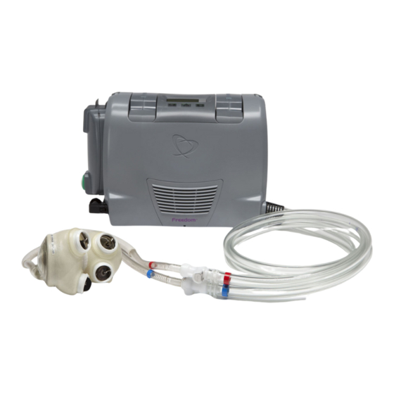
The SynCardia temporary Total Artificial Heart (TAH-t) System is comprised of an implantable TAH-t (50cc or 70cc) and an external driver, such as the Freedom Driver, that provides pneumatic power to the TAH-t (Figure 1-1). NOTE: The Freedom Driver System should be operated only by people... -
Page 10: Figure 1-2 - The Syncardia 70Cc Tah-T And 50Cc Tah-T
70cc TAH-t cannulae have one colored band on each cannula, as shown in Figure 1-2. For more information on the TAH-t, please refer to the SynCardia temporary Total Artificial Heart (TAH-t) Instructions for Use with the Companion 2 Driver System or CSS, for the 50cc or 70cc TAH-t, as appropriate. -
Page 11: Figure 1-3 - Freedom Driver With Attached Power Adaptor And Drivelines Connected To The Cannulae Of A Tah-T
Drivelines are connected directly to the TAH-t Cannulae via CPC connectors. The Freedom Driver uses visual indicators as well as visual and auditory alarms to give information about the state of the Driver. It is powered by... - Page 12 The only adjustable setting in the Freedom Driver is the driver operating rate (Beat Rate). The Beats per Minute (BPM) can only be adjusted at the Hospital by a SynCardia trained medical professional with tools designed specifically for this purpose (provided in the Clinician Tool Kit). The Clinician Tool Kit should never be given to the patient and the patient should never adjust his/her Beat Rate.
- Page 13 Section 10.3. While each driver has internal redundancy, each patient is issued a backup Freedom Driver. This backup Driver must accompany the patient at ALL times whether in the Hospital or out of the Hospital. It...
- Page 14 Driver. 1.3.4 Components of the Freedom Driver System The Freedom Driver System consists of the following parts: • One primary Driver with attached Power Adaptor • One backup Driver with attached Power Adaptor •...
- Page 15 CAUTION All of the above components of the Freedom Driver System are given to the patient upon Hospital discharge except the Freedom Hospital AC Power Supply, Clinician Tool Kit, the Permanent Center Tool Kit and the Dummy Battery that was inserted into the primary Freedom Driver.
-
Page 16: Figure 1-4 Exploded View Of The Freedom Driver System
Figure 1-4 Exploded View of the Freedom Driver System SynCardia Systems, LLC ® Freedom Driver System Operator Manual Page 16 of 170... -
Page 17: Figure 1-5 - Primary Freedom Driver With Attached Power Adaptor And Two Inserted Onboard Batteries
The primary Freedom Driver (Figure 1-5) is the Driver connected to the implanted TAH-t. • A Power Adaptor is attached on the side of the primary Freedom Driver and is needed to connect the Driver to an External Power source. - Page 18 Fault Alarm (solid light). The alarm is accompanied by an audible tone. • Power Adaptor: converts input power from External Power sources to DC power for use by the Freedom Driver. • Power Adaptor green light: when lit, confirms proper connection of the Freedom Driver to External Power.
- Page 19 See Section 10.3 for information on how to resolve Fault Alarms. CAUTION A backup Freedom Driver must always be available for the patient in the event that the primary Freedom Driver is dropped, exposed to liquid/debris, subjected to rough handling or has a Permanent Fault Alarm.
-
Page 20: Figure 1-6 - Backup Freedom Driver With Attached Power Adaptor And Inserted Dummy Battery
Figure 1-6 – Backup Freedom Driver with attached Power Adaptor and Inserted Dummy Battery 1.3.7 Power Adaptor The Power Adaptor (Figure 1-7) converts input power from External Power sources to DC power for use by the Freedom Driver. Electrical power is transmitted from the Power Adaptor to the Freedom Driver by a power cord. -
Page 21: Figure 1-7 - Power Adaptor
Whenever possible, connect the Freedom Driver to an External Power source to keep the Onboard Batteries fully charged. The Freedom Driver MUST be connected to External Power and the connection verified to be secure and the indicator lights on the Power Supply and Power Adaptor must be illuminated solid green before the patient goes to sleep. -
Page 22: Figure 1-8 - Onboard Battery
1.3.9 AC Power Supply 1.3.9.1 Hospital AC Power Supply The Freedom Hospital AC Power Supply is a Class I power supply unit which has an integrated, molded wall input power cord with a grounded plug (Figure 1-9). The Hospital AC Power Supply connects the Power Adaptor to a grounded wall power outlet. -
Page 23: Figure 1-9 - Hospital Ac Power Supply
Figure 1-9 – Hospital AC Power Supply 1.3.9.2 Home AC Power Supply The Freedom Home AC Power Supply is a Class II power supply unit which has an integrated, molded wall input power cord (Figure 1-10). The Home AC Power Supply connects the Power Adaptor to a wall power outlet. -
Page 24: Figure 1-10 - Home Ac Power Supply
Power Supply and Power Adaptor are illuminated solid green. The Home AC Power Supply is designed to accept electrical power input from 100VAC to 240VAC, and 50Hz/60Hz. Freedom Driver Systems will be shipped with region-appropriate AC Power Supplies. Figure 1-10 – Home AC Power Supply 1.3.9.3... -
Page 25: Figure 1-11 - Ac Power Supply And Cord
50Hz/60Hz. Freedom Driver Systems will be shipped with the appropriate power cords. Figure 1-11 – AC Power Supply and Cord 1.3.10 Car Charger The Car Charger (Figure 1-12) connects the Power Adaptor to a 12V vehicle power outlet. The Car Charger has an “on/off” switch on the end that plugs into the 12V vehicle power outlet. -
Page 26: Figure 1-12 - Car Charger
Onboard Batteries that are not in use in the Driver. The Battery Charger uses the same AC Power Supply and Cord as the Freedom Driver. Do not connect the Car Charger to the Battery Charger. - Page 27 It is recommended to keep the Handle Strap attached to the Freedom Driver. The Freedom Driver should be held by the Handle Strap when it is outside of the Shoulder Bag or Backpack. The Handle Strap should be used to insert or remove the Freedom Driver into or out of the Shoulder Bag or Backpack.
-
Page 28: Figure 1-14 - Dummy Battery
Freedom Driver. Insert only into a faulted primary Driver after the patient is connected to a properly functioning backup Driver. If the Dummy Battery is inserted in the primary Freedom Driver, a condition is created in which accidental removal of all power is possible, resulting in the Driver ceasing to provide life-sustaining support. -
Page 29: Figure 1-15 - Filter Pack, Screwdriver And Screws
The Patient Tool Kit (Figure 1-16) contains the following: Wire Ties • Used to prevent accidental disconnection of the CPC Connectors that secure the TAH-t Cannulae to the Freedom Drivelines. • They are inserted under the metal release button of the CPC connector. -
Page 30: Figure 1-16 - Patient Tool Kit
• The Freedom Driver with two inserted Onboard Batteries • The Power Adaptor • One Patient Tool Kit It is recommended to carry the primary Freedom Driver inside the Shoulder Bag or Backpack. Clinicians should evaluate the patient strength and recovery status before having the patient carry the bags. -
Page 31: Figure 1-17 - Shoulder Bag
Onboard Battery exchange. If the Freedom Driver is not properly secured inside the Freedom Shoulder Bag or Backpack, the Driver may fall and be damaged. If the Freedom Driver is dropped, exposed to liquid/debris or subjected to rough handling, it may sustain damage that will not allow it to provide life-sustaining functions as designed. - Page 32 • The top has a mesh window to view the Power Adaptor green light to confirm connection to External Power. • A rain cover is provided to temporarily protect the Freedom Driver from water (rain, sleet, snow, nearby shower/tub area, etc.) when the Driver is in the Shoulder Bag (Figure 1-19) or...
-
Page 33: Figure 1-19 - Shoulder Bag With Rain Cover
• One Patient Tool Kit It is recommended that patients take all accessories in the Accessory Bag when leaving the house. The Accessory Bag can be carried using the shoulder strap or by the handle. SynCardia Systems, LLC ® Freedom Driver System Operator Manual... -
Page 34: Figure 1-21 - Accessory Bag
1.3.18 Pelican Case The Pelican case (Figure 1-22) is a large hard plastic case (box) with foam padding on the inside that holds the primary and backup Freedom Driver and accessories during shipping. Figure 1-22 – Pelican Case SynCardia Systems, LLC ®... -
Page 35: Figure 1-23 - Clinician Tool Kit
This kit is intended to stay at the transplant center until a patient needs a new backup driver due to scheduled service or a fault alarm. After issuing the new Freedom Driver, the center should place the used driver in the kit and contact SynCardia for return instructions. 1.3.20 Clinician Tool Kit... -
Page 36: Figure 1-24 - Connector Kit
The Connector Kit is composed of CPC connectors and wire ties (Figure 1-24). Male and Female CPC connectors for the Cannulae • Inserted into the Cannulae during a CSS Console to Freedom Driver switch. Also provided as a spare in the event a connector needs to be replaced. - Page 37 Tool Kit is not available Additional Screws for Setting Dial Cover • Provided as spares should the screw for the Setting Dial Cover get lost during setup SynCardia Systems, LLC ® Freedom Driver System Operator Manual Page 37 of 170...
- Page 38 SynCardia Systems, LLC ® Freedom Driver System Operator Manual Page 38 of 170...
-
Page 39: Indications For Use
Freedom Driver System Intended Use The Freedom Driver System, used with the 50cc TAH-t or the 70cc TAH-t, is intended for in-hospital and out-of hospital use. The TAH-t System with the SynCardia Freedom Driver is indicated for use as a bridge to transplantation in cardiac transplant candidates who are implanted with the TAH-t and are clinically stable. - Page 40 Driver is designed to continue to provide its life-sustaining function when the driver is alarming • Avoid activities that may result in fall or injury to the patient and/or Freedom Driver. If the primary Freedom Driver is dropped or subjected to rough handling, the patient MUST switch to the backup Freedom Driver.
-
Page 41: Table 2-1 - Key Adverse Event Comparison Stable Pmss To Freedom In-Hospital Cohort
Tract Infection o Major Infection: Sepsis Result: The rate of occurrence of these three key AEs was lower in the Freedom Driver In-Hospital Cohort than the rate of occurrence experienced by the clinically stable PMSS Cohort while in the hospital. - Page 42 (did not delay or preclude transplant). This comparison supports the conclusion that the Freedom Driver is safe for use in the hospital environment. No subject deaths or preclusions from transplant occurred in subjects who remained in the hospital environment through their respective study endpoint.
-
Page 43: Table 2-2 - Adverse Event Comparison Stable Pmss To Freedom In-Hospital Experience
Hospital Driver is higher than that experienced by the subjects supported by the Freedom Driver System in the hospital. Table 2-2 Adverse Event Comparison Stable PMSS to Freedom In-Hospital – Experience Postmarket Surveillance Study SynCardia Freedom Driver System Study... - Page 44 Postmarket Surveillance Study SynCardia Freedom Driver System Study Clinically Stable Adverse Events (AEs) In-Hospital Adverse Events (AEs) All Clinically Stable Patients Results of In-Hospital AE Analysis AEs per AEs per Number (%) of Subject Subject ® ® Number intermacs intermacs...
- Page 45 0.00 Table 2-3 compares AE rates of the clinically stable PMSS Cohort (82 patients) to the cumulative Freedom Driver System Study experience (77 patients). The analysis includes the number of AEs in each AE category, the percentage of subjects/patients who experienced AEs, and the AE rate per subject year.
-
Page 46: Table 2-3 - Adverse Event Comparison Stable Pmss To Cumulative Freedom Experience
Table 2-3 Adverse Event Comparison Stable PMSS to Cumulative Freedom – Experience Postmarket Surveillance Study SynCardia Freedom Driver System Study Clinically Stable Adverse Events (AEs) Freedom Adverse Events (AEs) All Subjects on Freedom Driver All Clinically Stable Patients Support AEs per AEs per ®... - Page 47 Postmarket Surveillance Study SynCardia Freedom Driver System Study Clinically Stable Adverse Events (AEs) Freedom Adverse Events (AEs) All Subjects on Freedom Driver All Clinically Stable Patients Support AEs per AEs per ® ® Number (%) of intermacs intermacs Subject Subject...
- Page 48 Freedom Driver System support. The intent of this analysis was two-fold: • to demonstrate that the Freedom Driver can be used safely in the out-of-hospital environment, and • to demonstrate that patients and lay caregivers can use the device safely.
- Page 49 TAH-t supported by the Freedom Driver in the out-of- hospital environment. • Avoid kinking and tugging of drivelines • Examine cannulae exit sites during dressing changes and report changes in appearance to hospital personnel immediately • Inspect cannulae regularly and report cracks and/or air leaks to hospital personnel immediately •...
-
Page 50: Table 2-4 - Freedom Adverse Event Comparison In-Hospital To Out-Of-Hospital
Table 2-4 compares the adverse event profiles for Freedom Driver System use in and out of the hospital. This comparison shows that the overall rate of adverse events experienced outside of the hospital is lower than that experienced in-hospital. Table 2-4 Freedom Adverse Event Comparison In-Hospital to Out-of-Hospital –... - Page 51 SynCardia Freedom Driver System Study SynCardia Freedom Driver System Study In-Hospital AEs Out-of-Hospital AEs Results of Out-of-Hospital AE Results of In-Hospital AE Analysis Analysis AEs per AEs per Subject Subject ® ® Number (%) of intermacs intermacs Number Year Year...
- Page 52 SynCardia Freedom Driver System Study SynCardia Freedom Driver System Study In-Hospital AEs Out-of-Hospital AEs Results of Out-of-Hospital AE Results of In-Hospital AE Analysis Analysis AEs per AEs per Subject Subject ® ® Number (%) of intermacs intermacs Number Year Year...
-
Page 53: Table 2-5 - Adverse Event Comparison Freedom Experience High Volume Sites To Low Volume Sites
2.1.3 Additional Analysis Two centers that participated in the Freedom Driver System Study contributed approximately 40 percent of the subjects whose data were included in these results. This analysis includes four compassionate use patients. A comparison between the AE rate at these two centers to that at lower volume centers with less overall Freedom Driver System experience was conducted. - Page 54 SynCardia Freedom Driver System Study SynCardia Freedom Driver System Study High Volume Centers (N=2) Low Volume Centers (N=23) Results of AE Analysis Results of AE Analysis For High Volume Centers For Low Volume Centers AEs per AEs per ® intermacs Subject ®...
- Page 55 SynCardia Freedom Driver System Study SynCardia Freedom Driver System Study High Volume Centers (N=2) Low Volume Centers (N=23) Results of AE Analysis Results of AE Analysis For High Volume Centers For Low Volume Centers AEs per AEs per ® intermacs Subject ®...
- Page 56 The results of the Freedom Driver System Study demonstrate that, while adverse events may occur in the out-of-hospital environment, the Freedom Driver System is appropriate for its intended use. When used in the clinically stable TAH-t patient population, the Freedom Driver System: •...
-
Page 57: Contraindications
• Patients who have a body surface area (BSA) of > 1.85 m • Patients who cannot be adequately anticoagulated on the 50cc TAH-t. The Freedom Driver System is contraindicated for use in TAH-t patients who are not clinically stable. - Page 58 SynCardia Systems, LLC ® Freedom Driver System Operator Manual Page 58 of 170...
-
Page 59: Warnings
Fault Alarm, immediately inspect the Drivelines for kinks or damage. • A reduction in the Fill Volume on the Freedom Driver Display to below 30 milliliters may indicate a failure of one of the diaphragms in an artificial ventricle of the 50cc TAH-t. - Page 60 MUST switch to the backup Freedom Driver. • If the Freedom Driver or any of the accessories are dropped, they must be brought back to the Hospital for replacement. • Always keep the Freedom Driver System out of reach of infants, children and pets.
- Page 61 Permanent Fault Alarm. If the primary Freedom Driver is dropped, exposed to liquid/debris, subjected to rough handling or if the Fault Alarm cannot be resolved within three to four minutes, the patient must switch to the backup Freedom Driver.
- Page 62 SynCardia Systems, LLC ® Freedom Driver System Operator Manual Page 62 of 170...
-
Page 63: Precautions And Recommendations
• Avoid exposing the Freedom Driver System to extreme temperatures for more than brief periods of time. • Do not block the Filter Cover and Fan of the Freedom Driver with any object that might block air flow. • The patient must avoid being in loud environments (i.e. loud music, arenas, etc.) that might prevent them from hearing an Alarm from the... - Page 64 • It is recommended to have two people (patient and trained caregiver) exchange the primary Freedom Driver for the backup Freedom Driver. • It is recommended that the Freedom Driver has at least two sources of power to operate. Plug in the Freedom Driver to an External Power source when replacing an Onboard Battery.
-
Page 65: Operating Instructions
Hospital. Equipment the Patient Needs to Leave the Hospital The patient must go home with a primary and a backup Freedom Driver that have been checked out per the Test Protocol in Appendix 2. The Test Protocol must be conducted at the hospital by a trained hospital technical support team before connecting the patient to the Driver. - Page 66 • Filter Pack • Quick Guide and Emergency Card CAUTION A backup Freedom Driver must always be available in the event that the primary Freedom Driver is dropped, exposed to liquid/debris, subjected to rough handling or has a Permanent Fault Alarm.
- Page 67 Power Management It is recommended that the Freedom Driver have at least two sources of power: • Power from both Onboard Batteries, or • Power from both Onboard Batteries and connection to an External Power source. The Freedom Driver requires at least one source of power at all times: •...
- Page 68 External Power provides power to operate the Freedom Driver and simultaneously charges the Onboard Batteries. External power is provided to the Freedom Driver when the Power Adaptor is connected to wall power via the AC Power Supply or connected to a 12V vehicle power outlet via the Car Charger.
-
Page 69: Figure 6-1 - Unplugging The Power Adaptor From The Freedom Driver
• The Power Adaptor needs to be attached to the Freedom Driver, • The green connector from either the AC Power Supply or Car Charger needs to be connected to the Power Adaptor, and • The AC Power Supply or Car Charger must be plugged in to an External Power source (wall power outlet or 12V vehicle power outlet). -
Page 70: Figure 6-2 - Removing The Power Adaptor From The Freedom Driver
• Plug the Power Adaptor cord into the outlet on the left side of the Driver 6.4.2 Using Wall Power through the Power Adaptor The Freedom Driver should be connected to a wall power outlet via the AC Power Supply whenever possible to ensure that the Onboard Batteries remain charged. -
Page 71: Figure 6-3 - Plugging The Green Connector Into The Green Power Adaptor Receptacle
• Confirm that the light on the Power Adaptor is illuminated solid green to ensure that a proper connection to External Power has been made. The proper connection of the Freedom Driver to a wall power outlet is shown in (Figure 6-4). Connections Green Lights Figure 6-4 –... - Page 72 If the green light on the Power Adaptor is off, then the Freedom Driver is not properly connected to an External Power source and is using Onboard Battery power. If the green light fails to light up on the Power Adaptor: •...
- Page 73 External Power has been made. If the green light on the Power Adaptor is off, then the Freedom Driver is not properly connected to an External Power source and is using Onboard Battery power.
- Page 74 6.4.5 Charging Spare Onboard Batteries through the Power Adaptor It is recommended that only one spare Onboard Battery be charged in the Freedom Driver at a time to avoid a Battery Alarm from occurring. To charge additional spare Onboard Batteries and to ensure continuous power to the Freedom Driver, follow these steps: •...
- Page 75 15 seconds after the Driver has been connected to External Power. NOTE: The Freedom Driver charges the battery with the lowest charge first. Only the charging battery will show a blinking green light when the Battery Fuel Gauge is illuminated. Batteries at the same charge level are charged alternately until both are fully charged.
-
Page 76: Figure 6-5 - Removing The Green Connector From The Green Power Adaptor Receptacle
Batteries are a chargeable source of power that allows the patient to move freely in or out of the house. Whenever possible, connect the Freedom Driver to an External Power source to keep the Onboard Batteries fully charged. The patient must always carry at least two additional fully charged Onboard Batteries. - Page 77 Driver will automatically alternate charging between Battery 1 and Battery 2. Plug in the Freedom Driver to an External Power source when replacing an Onboard Battery. • If connection to External Power is not available, make sure to promptly insert another charged Onboard Battery into the Freedom Driver.
-
Page 78: Figure 6-6 - Battery Fuel Gauge
• Insert the Onboard Battery in the Onboard Battery Well, such that the Battery Charge Button and the Battery Release Button on the Freedom Driver are next to each other (Figure 6-7). • Push down on the Onboard Battery until the battery is locked in place. -
Page 79: Figure 6-7 Correct Onboard Battery Insertion Into Battery Well
Figure 6-7 Correct Onboard Battery Insertion into Battery Well 6.5.3 Removing Onboard Batteries The Freedom Driver has a mechanism that locks one Onboard Battery into the Driver at all times. This mechanism prevents the user from accidentally removing both Onboard Batteries at the same time. -
Page 80: Figure 6-8 - Battery Charger And Bays
Using the Battery Charger The Freedom Battery Charger (Part Number 295054-001) is an accessory to the Freedom Driver System. The Battery Charger has four battery bays (Figure 6-8) that accommodate Freedom Onboard Batteries. It is intended to be used as an alternative source of battery charging for the Onboard Batteries for the Freedom Driver System. - Page 81 • Only Onboard Batteries shall be placed into the battery bays. No other objects shall be placed into any battery bay. • Do not use the Freedom Car Charger with the Battery Charger. • It is important to keep the battery bays free of debris and liquid.
-
Page 82: Figure 6-10 - Driver Lcd Screen
Beat Rate (BPM) of the Driver to accommodate the patient’s TAH-t requirements. It is important for the patient to check the Freedom Driver several times every day, to make sure that the values displayed on the screen are correct as recommended by the Hospital Contact Person. - Page 83 Low Battery Alarm occurs. 6.7.4 Power Indicator Lights The Freedom Power Adaptor has a solid green Indicator Light in the upper right corner which will illuminate when it is receiving power from either the AC Power Supply or the Car Charger and when the Power Adaptor is connected to the Driver.
- Page 84 Green Indicator Lights on the AC Power Supply and Car Charger illuminate to indicate proper function of the equipment when connected to an electrical power source. SynCardia Systems, LLC ® Freedom Driver System Operator Manual Page 84 of 170...
-
Page 85: Preparing The Freedom Driver For Patient Use
In addition, the Hospital will receive a box containing an additional Hospital AC Power Supply, three bags (Shoulder Bag, Backpack, and Accessory Bag) that the patient will use to carry the Freedom Driver System. The trained Hospital staff will explain the use of the Freedom Bags and the use of the accessories to the patient. - Page 86 125 BPM and, if necessary, must be adjusted as needed for the patient. CAUTION Both primary and backup Freedom Drivers must be tested at the Hospital prior to use, following the checklist for the Freedom Driver Test Protocol (Appendix 2).
-
Page 87: Table 7-1 - Normotensive Settings - Patient Simulator
The completed checklist must be sent by FAX to SynCardia Systems, LLC at the fax number: 520-903-1782, also listed on the form. In order to perform the Freedom Driver System Test Protocol (Appendix 2), the Driver must be connected to a 70cc TAH-t and to a Patient Simulator (also referred to as Mock Tank) set to normotensive settings, as specified in Table 7-1. -
Page 88: Figure 7-1 - Driveline Caps
Driver and feel air coming out of the Drivelines) • Connect the Freedom Driver to a Patient Simulator to avoid alarms • Connect the Freedom Driver into a wall power outlet using the AC Power Supply cord •... -
Page 89: Figure 7-2 - Beat Rate Setting Dial On The Back Of The Freedom Driver
Access to setting dial Figure 7-2 – Beat Rate Setting Dial on the Back of the Freedom Driver The Beat Rate of the Driver will typically be set to around 120-135 beats per minute. The rate may be varied to meet the need of the patient. - Page 90 • Disconnect the Drivelines from the Patient Simulator and remove the AC Power Supply cord from the wall. • Turn off the Freedom Driver while moving it to the patient’s room: remove one Onboard Battery, replace it with the Dummy Battery and remove the second Onboard Battery.
- Page 91 • Make sure that the Driveline caps are attached to the ends of the Drivelines • Place the items that will be going home with the patient in the Freedom bags. Take the backup Driver, with the installed Dummy Battery, together with the loaded Accessory Bag, to the patient’s room when switching a patient...
- Page 92 SynCardia Systems, LLC ® Freedom Driver System Operator Manual Page 92 of 170...
-
Page 93: List Of Symbols
List of Symbols Refer to Table 8-1 for a description of the symbols used in Visual Alarms and in labels of the Freedom Driver System. Table 8-1 –Symbols Used in the Freedom Driver System Symbol Description Symbol Description Temperature Alarm or... - Page 94 P: Cell shape ( P= Prismatic) 6: Maximum thickness of cell (in mm) 65: Maximum width of cell (in mm) 96: Maximum height of cell (in mm) SynCardia Systems, LLC ® Freedom Driver System Operator Manual Page 94 of 170...
-
Page 95: Freedom Driver Operating Cautions
Use of SynCardia-Approved Components Only The Freedom Driver System and the TAH-t have been developed, tested and approved as a System. Use of the Freedom Driver is authorized only in conjunction with related equipment described in this document. Tamper Evident Seal Do not open the back panel of the Driver. - Page 96 Freedom Driver before attempting to operate the System. • Keep the Freedom Driver dry. Protect it from showers, baths, rain and liquid/debris. If the Freedom Driver is exposed to liquid/debris, it must be exchanged for the backup Freedom Driver.
- Page 97 CSS Consoles should be indicated on the Freedom Driver System Test Protocol (Appendix 2) along with the serial numbers of the primary and backup Freedom Drivers. • The Freedom Driver System Test Protocol should be faxed to SynCardia Systems, LLC. 9.13 Patient Preparation for Excursions...
- Page 98 • Wire Cutter Tool CAUTION A backup Freedom Driver must always be available in the event that the primary Freedom Driver is dropped, exposed to liquid/debris, subjected to rough handling or has a Fault Alarm that cannot be resolved per the instruction in Section 10.3.
-
Page 99: Visual And Audible Alarms
• A Visual Alarm (blinking or solid colored light), and • An Audible Alarm (beeping or constant tone). There are three kinds of Alarms that can occur with the Freedom Driver, listed in order of lowest to highest priority, they are: •... - Page 100 • Reinsert incorrectly installed Onboard Battery until locked in place. If the Battery Alarm continues, insert a new Onboard Battery • If an Onboard Battery is removed from the Freedom Driver, then insert a charged Onboard Battery into the Driver.
- Page 101 Low Battery Alarm occurs. Actual support time may vary according to Driver Beat Rate setting. The Onboard Batteries will eventually lose power and the Freedom Driver will not function if it is not connected to External Power. CAUTION Do not ignore a Battery Alarm.
-
Page 102: Figure 10-2 - Illuminated Flashing Red Temperature Alarm Light
A Temperature Alarm is indicated by a beeping tone Audible Alarm and a blinking red light Visual Alarm on the top of the Freedom Driver (Figure 10-2). The volume of the Audible Alarm is in the range of 82 to 93 decibels (depending on the user’s location with respect to the Driver). -
Page 103: Figure 10-3 - Illuminated Solid Red Fault Alarm Light
A Fault Alarm (Figure 10-3) is indicated by a constant tone Audible Alarm and a solid red light Visual Alarm on the top of the Freedom Driver. The volume of the Audible Alarm is in the range of 85 to 96 decibels (depending on the user’s location with respect to the Driver). - Page 104 Drivelines, the Drivelines and Cannulae are connected, and the Battery Alarm has not been ignored, then a malfunction of the Freedom Driver exists and the patient must switch to the backup Freedom Driver immediately, following instruction in SynCardia Systems, LLC ®...
- Page 105 Section 11, Switch from Primary Freedom Driver to Backup Freedom Driver. CAUTION Do not ignore a Fault Alarm. If a Fault Alarm cannot be resolved within three to four minutes, it may become a Permanent Fault Alarm that requires switching to the backup Freedom Driver.
- Page 106 SynCardia Systems, LLC ® Freedom Driver System Operator Manual Page 106 of 170...
-
Page 107: Switch From Primary Freedom Driver To Backup Freedom Driver
Freedom Driver. The patient must switch to the backup Freedom Driver if a Fault Alarm (indicated by a constant tone Audible Alarm and a solid red Visual Alarm) occurs and cannot be resolved by performing the following: •... - Page 108 11.2 Preparation to Perform Switch from Primary to Backup Freedom Driver If possible, plug the primary Freedom Driver into a wall power outlet using the AC Power Supply. If connecting to wall power, confirm that the light on the Power Adaptor is illuminated solid green to ensure a proper connection.
- Page 109 Driver and feel air coming out of the Drivelines) NOTE: The Freedom Driver is set up not to activate a Fault Alarm for low Cardiac Output for 15 minutes after it has been initially turned on, to allow time to connect to a TAH-t.
-
Page 110: Figure 11-1 - Freedom Drivelines Connected To Cannulae Via The Cpc Connectors
Metal Release Driveline Button with Wire Tie Figure 11-1 – Freedom Drivelines Connected to Cannulae via the CPC Connectors DO NOT DISCONNECT THE CANNULA FROM THE DRIVELINE YET. With the Wire Cutter Tool provided in the Tool Kit, cut the Wire Tie... -
Page 111: Figure 11-2 - Cutting The Wire Tie With The Wire Cutter Tool
CAUTION Before disconnecting the Drivelines of the primary Freedom Driver, you must have the Drivelines of the backup Freedom Driver within reach. Perform steps 4 and 5 simultaneously in order to disconnect the Drivelines of the primary Freedom Driver and connect the Drivelines of the backup Freedom Driver (Figures 11-3 and 11-4). -
Page 112: Figure 11-3 - Disconnecting The Drivelines From The Cannulae
Simultaneously, disconnect the blue Cannula from the blue Driveline of the primary Freedom Driver: • Press and hold down the metal release button, • Pull the blue Cannula away from the blue Driveline, • Immediately insert the blue Cannula into the new... -
Page 113: Figure 11-5 - Inserting Wire Tie Under Metal Release Button Of Cpc Connector
If a Wire Tie is unavailable, the patient must be careful NOT to accidentally disconnect the Drivelines from the Cannulae. The patient must go to the Hospital to return the faulted Freedom Driver and be issued a new backup Freedom Driver. - Page 114 CAUTION Some faults may cause the Freedom Driver to not charge the Batteries. If the patient travels to the Hospital with a Freedom Driver with a Fault Alarm, they must plug the Driver into vehicle power to maintain the Onboard Batteries.
-
Page 115: Switch From Css Console To Primary Freedom Driver
The switch from CSS Console to Primary Freedom Driver should be performed by trained clinicians only and should not be performed by patients. 12.1 Materials Prior to switching the patient from the CSS Console to the Freedom Driver System, the following must be available: • One prepared primary Freedom Driver •... -
Page 116: Figure 12-1 - Inserting Wire Tie Under Metal Release Button Of Cpc Connector
Driver and feel air coming out of the Drivelines) NOTE: The Freedom Driver is set up not to activate a Fault Alarm for low Cardiac Output for 15 minutes after it has been initially turned on, to allow time to connect to a TAH-t. -
Page 117: Figure 12-2 - Wire Ties Around Css Hose Barb Connectors
CAUTION If the Fault Alarm comes on immediately upon powering up the Freedom Driver, there is a malfunction of the Driver. The patient must not be switched from the CSS Console to the Freedom Driver. CAUTION When performing a switch from the CSS Console to the Freedom Driver, make certain the Drivelines are properly connected to the TAH-t Cannulae, and do not kink the Drivelines. -
Page 118: Figure 12-3 - Metal Hose Barb Connectors Loosened, But Still Connected, To The Cannulae
Cannula by pulling and then immediately insert the CPC connector of the blue Freedom Driveline into the blue Cannula (Figure 12-4). Push in Push in Figure 12-4 - Inserting the Freedom Drivelines into the Cannulae SynCardia Systems, LLC ® Freedom Driver System Operator Manual Page 118 of 170... -
Page 119: Figure 12-5 - Securing Cannulae To Cpc Connectors With Wire Ties
Modify the CSS Console Drivelines for potential reuse: NOTE: In order to modify CSS Console Drivelines for potential reuse with a Freedom patient, you will need special CSS Console Driveline CPC Connectors (the CPC Connectors in the Connector Kit cannot be used for this modification). If you would like to modify CSS Console Drivelines, please contact SynCardia Systems to obtain the proper connectors. -
Page 120: Figure 12-6 - Cut Driveline Tubing
Insert the female CSS Console Driveline CPC Connector into the blue Driveline. Secure with at least two wire ties (Figure 12- Female CPC Connector secured with two wire ties Figure 12-8 – Female CPC Connector SynCardia Systems, LLC ® Freedom Driver System Operator Manual Page 120 of 170... -
Page 121: Figure 12-9 - Driveline End Comparison
The final Modified CSS Console Driveline is shown in Figure 12-10. Female CPC Connector on blue Driveline Male CPC Connector Driveline Figure 12-9 – Driveline End Comparison Figure 12-10 – Modified CSS Console Driveline SynCardia Systems, LLC ® Freedom Driver System Operator Manual Page 121 of 170... - Page 122 Hospital to switch the patient back to a CSS Console, if necessary. The Hospital should notify SynCardia Systems Clinical Support that the patient has been switched from the CSS Console to the Freedom Driver.
-
Page 123: Switch From Freedom Driver To Css Console
Freedom Driver to the CSS Console. Make sure all items and accessories are closely available before exchanging Drivers. The switch from a Freedom Driver to a CSS Console should be performed by trained clinicians only and should not be performed by patients. 13.1 Materials... -
Page 124: Figure 13-1 - Connection Of Driver Connectors To Cannulae
With the Wire Cutter Tool provided in the Tool Kit, cut the Wire Tie under the metal release button of the CPC Connector that secures TAH-t Cannula to the Freedom Driveline (Figure 13-2). Gently pull to remove the Wire Tie and discard. Wire Tie Figure 13-2 –... - Page 125 Gently pull to remove the Wire Tie and discard. CAUTION Before disconnecting the Drivelines of the Freedom Driver, you must have the Modified Drivelines of the CSS Console within reach. Perform steps 4 and 5 simultaneously in order to disconnect the Drivelines of the Freedom Driver and connect the Modified Drivelines of the CSS Console (Figures 13-3 and 13-4).
-
Page 126: Figure 13-3 - Disconnecting Freedom Drivelines From The Cannulae
Pull Press Press Pull Pull Figure 13-3 – Disconnecting Freedom Drivelines from the Cannulae Push in Push in Figure 13-4 – Connecting the Modified CSS Console Drivelines to the Cannulae Slide a Wire Tie under the metal release button of each CPC connector (Figure 13-5). -
Page 127: Figure 13-5 - Inserting Wire Tie Under Metal Release Button Of Cpc Connector
Figure 13-5 – Inserting Wire Tie under Metal Release Button of CPC Connector The Hospital should notify SynCardia Systems that the patient has been switched. SynCardia Systems, LLC ® Freedom Driver System Operator Manual Page 127 of 170... - Page 128 SynCardia Systems, LLC ® Freedom Driver System Operator Manual Page 128 of 170...
-
Page 129: Switch From Css Console With Modified Drivelines To Freedom Driver
Driver and feel air coming out of the Drivelines) NOTE: The Freedom Driver is set up not to activate a Fault Alarm for low Cardiac Output for 15 minutes after it has been initially turned on, to allow time to connect to a TAH-t. -
Page 130: Figure 14-1 - Connection Of Modified Css Console Driveline To Cannulae
CAUTION If the Fault Alarm comes on immediately upon powering up the Freedom Driver, there is a malfunction of the Driver. The patient must not be switched from the CSS Console to the Freedom Driver. CAUTION When performing a switch from the CSS Console to the Freedom Driver, make certain the Drivelines are properly connected to the TAH-t Cannulae, and do not kink the Drivelines. -
Page 131: Figure 14-2 - Cutting The Wire Tie With The Wire Cutter Tool
CAUTION Before disconnecting the Modified Drivelines of the CSS Console, you must have the Drivelines of the operating Freedom Driver within reach. Perform steps 4 and 5 simultaneously in order to disconnect the Modified Drivelines of the CSS Console and connect the Drivelines of the Freedom Driver (Figures 14-3 and 14-4). -
Page 132: Figure 14-3 - Disconnecting Modified Css Console Drivelines From The Cannulae
Press Press Pull Pull Figure 14-3 – Disconnecting Modified CSS Console Drivelines from the Cannulae Push Push Figure 14-4 – Connecting the Freedom Drivelines to the Cannulae SynCardia Systems, LLC ® Freedom Driver System Operator Manual Page 132 of 170... -
Page 133: Figure 14-5 - Inserting Wire Tie Under Metal Release Button Of Cpc Connector
Retention Bag. The patient’s name and the date of the switch must be written on the bag and retained by the Hospital to switch the patient back to the CSS Console, if necessary. The Hospital should notify SynCardia Systems that the patient has been switched. SynCardia Systems, LLC ®... - Page 134 SynCardia Systems, LLC ® Freedom Driver System Operator Manual Page 134 of 170...
-
Page 135: Switch From Companion 2 Driver To Freedom Driver
Driver to the Freedom Driver. Make sure all items and accessories are available before exchanging Drivers. The switch from a Companion 2 Driver to a Freedom Driver should be performed by trained clinicians only and should not be performed by patients. 15.1 Materials... - Page 136 Driver and feel air coming out of the Drivelines) NOTE: The Freedom Driver is set up not to activate a Fault Alarm for low Cardiac Output for 15 minutes after it has been initially turned on, to allow time to connect to a TAH-t.
-
Page 137: Figure 15-1 - Companion Drivelines Connected To Cannulae Via The Cpc Connectors
CPC Connector that secures TAH-t Cannula to the Companion Driveline (Figure 15- Gently pull to remove the Wire Tie and discard. SynCardia Systems, LLC ® Freedom Driver System Operator Manual Page 137 of 170... -
Page 138: Figure 15-2 - Cutting The Wire Tie With The Wire Cutter Tool
CAUTION Before disconnecting the Drivelines of the Companion 2 Driver, you must have the Drivelines of the Freedom Driver within reach. Perform steps 4 and 5 simultaneously in order to disconnect the Drivelines of the Companion 2 Driver and connect the Drivelines of the Freedom Driver (Figures 15-3 and 15-4). -
Page 139: Figure 15-3 - Disconnecting The Companion Drivelines From The Cannulae
Press Pull Pull Figure 15-3 – Disconnecting the Companion Drivelines from the Cannulae Push in Push in Figure 15-4 – Connecting the Freedom Drivelines to the Cannulae SynCardia Systems, LLC ® Freedom Driver System Operator Manual Page 139 of 170... -
Page 140: Figure 15-5 - Inserting Wire Tie Under Metal Release Button Of Cpc Connector
Hospital to switch the patient back to the Companion 2 Driver, if necessary. The Hospital should notify SynCardia Systems that the patient has been switched from the Companion 2 Driver to the Freedom Driver. SynCardia Systems, LLC ®... -
Page 141: Switch From Freedom Driver To A Companion 2 Driver
Companion 2 Driver. Make sure all items and accessories are available before exchanging Drivers. The switch from a Freedom Driver to a Companion 2 Driver should be performed by trained clinicians only and should not be performed by patients. 16.1 Materials... -
Page 142: Figure 16-1 - Freedom Drivelines Connected To Cannulae Via The Cpc Connectors
Metal Release Driveline Button with Wire Tie Figure 16-1 – Freedom Drivelines Connected to Cannulae via the CPC Connectors DO NOT DISCONNECT THE CANNULA FROM THE DRIVELINE YET. With the Wire Cutter Tool provided in the Tool Kit, cut the Wire Tie... -
Page 143: Figure 16-2 - Cutting The Wire Tie With The Wire Cutter Tool
Drivelines of the Companion 2 Driver within reach. Perform steps 4 and 5 simultaneously in order to disconnect the Drivelines of the Freedom Driver and connect the Drivelines of the Companion 2 Driver (Figures 16-3 and 16-4). Disconnect the... -
Page 144: Figure 16-3 - Disconnecting The Freedom Drivelines From The Cannulae
• Lightly tug on the connection to make sure that it is secure. Pull Pull Press Press Pull Pull Figure 16-3 – Disconnecting the Freedom Drivelines from the Cannulae Push in Push in Figure 16-4 – Connecting the Companion Drivelines to the Cannulae SynCardia Systems, LLC ® Freedom... -
Page 145: Figure 16-5 - Inserting Wire Tie Under Metal Release Button Of Cpc Connector
Driver. Figure 16-5 – Inserting Wire Tie under Metal Release Button of CPC Connector The Hospital should notify SynCardia Systems that the patient has been switched from the Freedom Driver to the Companion 2 Driver. SynCardia Systems, LLC ®... - Page 146 SynCardia Systems, LLC ® Freedom Driver System Operator Manual Page 146 of 170...
-
Page 147: Equipment Maintenance And Care
CAUTION DO NOT soak any item of the Freedom Driver during cleaning. DO NOT allow water to come in direct contact with the Freedom Driver electrical connections to avoid shock or electrocution. If the Freedom Driver is exposed to liquid/debris, it MUST be exchanged for the backup Freedom Driver. -
Page 148: Figure 17-1 - Filter Cover
Filters may be rinsed for re-use if there are no holes or tears. To clean the filter, rinse using cold water. Allow to air dry before use. Additional Filter Packs can be reordered from SynCardia Systems, LLC. Filter Cover Figure 17-1 – Filter Cover 17.2.4 Onboard Batteries... - Page 149 • Do not disassemble or modify the Onboard Batteries. • Do not use Onboard Batteries as a power supply for anything other than the Freedom Driver System. • Do not charge an Onboard Battery using anything other than a Driver or other specified equipment.
- Page 150 Hospital Contact Person. CAUTION Keep objects and liquids that could fall into the Battery Wells away from the Freedom Driver. Failure to do so may cause the Freedom Driver to malfunction. 17.2.6 Battery Charger • Before cleaning, always disconnect the AC Power Supply from the Battery Charger.
- Page 151 The backup Freedom Driver and accessories should be stored in the Backpack or Shoulder Bag (whichever is not in use with the Primary Driver) in a cool, dry area. 17.4 Return of the Freedom Driver System When the patient receives a heart transplant, the patient must return the Freedom Driver and all accessories to the Hospital.
- Page 152 SynCardia Systems, LLC ® Freedom Driver System Operator Manual Page 152 of 170...
-
Page 153: Freedom Driver System Specifications
Freedom Driver System Specifications 18.1 Driver System Safety Standards • The Freedom Driver, as part of the SynCardia TAH-t and Freedom Driver System, has been tested pursuant to the requirements of the following standards: • IEC 60601-1: 1988, Medical electrical equipment – Part 1: General requirements for safety. - Page 154 AND MECHANICAL HAZARDS ONLY IN ACCORDANCE WITH IEC 60601-1 The Freedom Driver System has been tested and found to comply with the limits for medical devices to the IEC 60601-1-2:2001 - Medical electrical equipment − Part 1-2: General requirements for safety − Collateral standard: Electromagnetic compatibility.
-
Page 155: Table 18-2 - Declaration Concerning General Safety Standards For The Battery Charger
18.2 Battery Charger Safety Standards • The Battery Charger, as part of the Freedom Driver System, has been tested pursuant to the requirements of the following standards: o IEC 60601-1-2: 2007, Medical electrical equipment Part 1-2: General requirements for basic safety and essential performance –... -
Page 156: Table 18-3 - Guidance And Manufacturer's Declaration - Electromagnetic Emissions
Complies emissions IEC61000-3- The Freedom Battery Charger has been tested and found to comply with the limits for medical devices to the IEC 60601-1-2:2007 - Medical electrical equipment − Part 1-2: General requirements for safety − Collateral standard: Electromagnetic compatibility. -
Page 157: Table 18-4 - Declaration And Guidance Concerning Electromagnetic Immunity For The Freedom Battery Charger For Iec 60601-1-2
Declaration and Guidance Concerning Electromagnetic Immunity for The Freedom Battery Charger The Freedom Battery Charger is intended for use in the electromagnetic environment specified below. The customer or the user of the Battery Charger should assure that it is used in such an environment. -
Page 158: Table 18-5 - Declaration And Guidance Concerning Electromagnetic Immunity For The Freedom Battery Charger For Iec 60601
If the measured field strength in the location in which the Freedom is used exceeds the applicable RF compliance level above, Freedom should be observed to verify normal operation. If abnormal performance is observed, additional measures may be necessary, such as re- orienting or relocating the device. - Page 159 • Transportation/Storage Humidity: 10 – 95% RH (non-condensing) • Vibration: 0.75 G peak, 5 Hz to 500 Hz (three orthogonal axes, sweep at 1 octave/min 5 min dwell at four major resonances) SynCardia Systems, LLC ® Freedom Driver System Operator Manual...
-
Page 160: Table 18-6 - Input / Output Characteristics
• Right Drive Pressure (fixed): 110 mmHg • Diastolic Vacuum (fixed): -10 mmHg • Systolic Duration (fixed): 50% 18.10 Input / Output Characteristics Table 18-6 describes the input/output characteristics of the Freedom Driver System. Table 18-6 – Input / Output Characteristics Connection... - Page 161 18.11 Classification for Freedom Driver System • Class II Equipment; can also be used with Class I Hospital AC Power Supply • Type BF Equipment • Driver Ingress Protection: o Driver - IP30 o Driver in Shoulder Bag/Backpack with Rain Cover – IP32 •...
-
Page 162: Table 18-7 - Ip Rating Classification
Protected against the effects of continuous immersion in water Protected against high pressure and temperature water jets 18.15 Firmware Versions • Safety Monitor Firmware V1.14 • Display Firmware V1.02 SynCardia Systems, LLC ® Freedom Driver System Operator Manual Page 162 of 170... - Page 163 Appendix 1 Patient Information Card Template SynCardia Systems, LLC ® Freedom Driver System Operator Manual Page 163 of 170...
- Page 164 SynCardia Systems, LLC ® Freedom Driver System Operator Manual Page 164 of 170...
- Page 165 Appendix 1 Patient Information Card Template SynCardia Systems, LLC ® Freedom Driver System Operator Manual Page 165 of 170...
- Page 166 SynCardia Systems, LLC ® Freedom Driver System Operator Manual Page 166 of 170...
- Page 167 Appendix 2 Freedom Driver System Test Protocol SynCardia Systems, LLC ® Freedom Driver System Operator Manual Page 167 of 170...
- Page 168 SynCardia Systems, LLC ® Freedom Driver System Operator Manual Page 168 of 170...
- Page 169 Disconnect the Freedom Driver from Patient Simulator................YES NO Turn off primary Freedom Driver and restore Driveline caps while moving it to the patient’s room..... YES NO If any of the answers above are “No”, do not connect the patient and call Clinical Support Hotline Number +49-700- 796227342 or +1 866-771-9437 or +1-520-545-1234 for US.
- Page 170 BPM set on backup Driver to match BPM on primary Driver…………………………………………………. YES NO Attach Tamper Evident Label over the setting dial cover of both primary and backup Freedom Drivers… YES NO Place Patient Info Card and Quick Guide into Shoulder Bag and Backpack……………………………….. YES ...
- Page 171 Appendix 3 Freedom Battery Charger Operational Check Form SynCardia Systems, LLC Freedom® Driver System Operator Manual Page 169 of 170...
- Page 172 SynCardia Systems, LLC Freedom® Driver System Operator Manual Page 170 of 170...
- Page 173 If the Troubleshooting Instructions do not correct the problem, please contact the SynCardia Systems, LLC Help Line at (866) 771-9437. Send a copy of this form to SynCardia Systems, LLC by FAX to 520-903-1782 Performed By: _____________________________________________ Date: _____________ F-900013-EN Rev 004 Freedom®...
- Page 174 If these Troubleshooting Instructions did not correct the problem, please contact the SynCardia Systems, LLC Help Line at (866) 771-9437. F-900013-EN Rev 004 Freedom® Driver System Operator Manual Revision Date: 2017-05 ® SynCardia Systems, LLC Freedom...
Need help?
Do you have a question about the Freedom and is the answer not in the manual?
Questions and answers