Sign In
Upload
Manuals
Brands
SynCardia Manuals
Medical Equipment
Freedom
SynCardia Freedom Manuals
Manuals and User Guides for SynCardia Freedom. We have
1
SynCardia Freedom manual available for free PDF download: Operator's Manual
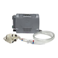
SynCardia Freedom Operator's Manual (174 pages)
Brand:
SynCardia
| Category:
Medical Equipment
| Size: 2 MB
Table of Contents
Table of Contents
3
Device Description
9
Figure 1-1 - 50Cc or 70Cc TAH-T with the Freedom Driver System
9
Figure 1-2 - the Syncardia 70Cc TAH-T and 50Cc TAH-T
10
Figure 1-3 - Freedom Driver with Attached Power Adaptor and Drivelines Connected to the Cannulae of a TAH-T
11
Figure 1-4 Exploded View of the Freedom Driver System
16
Figure 1-5 - Primary Freedom Driver with Attached Power Adaptor and Two Inserted Onboard Batteries
17
Figure 1-6 - Backup Freedom Driver with Attached Power Adaptor and Inserted Dummy Battery
20
Figure 1-7 - Power Adaptor
21
Figure 1-8 - Onboard Battery
22
Figure 1-9 - Hospital AC Power Supply
23
Figure 1-10 - Home AC Power Supply
24
Figure 1-11 - AC Power Supply and Cord
25
Figure 1-12 - Car Charger
26
Figure 1-13 - Battery Charger
26
Figure 1-14 - Dummy Battery
28
Figure 1-15 - Filter Pack, Screwdriver and Screws
29
Figure 1-16 - Patient Tool Kit
30
Figure 1-17 - Shoulder Bag
31
Figure 1-18 - Backpack
31
Figure 1-19 - Shoulder Bag with Rain Cover
33
Figure 1-20 - Backpack with Rain Cover
33
Figure 1-21 - Accessory Bag
34
Figure 1-22 - Pelican Case
34
Figure 1-23 - Clinician Tool Kit
35
Figure 1-24 - Connector Kit
36
Indications for Use
39
Table 2-1 - Key Adverse Event Comparison Stable PMSS to Freedom In-Hospital Cohort
41
Table 2-2 - Adverse Event Comparison Stable PMSS to Freedom In-Hospital Experience
43
Table 2-3 - Adverse Event Comparison Stable PMSS to Cumulative Freedom Experience
46
Table 2-4 - Freedom Adverse Event Comparison In-Hospital to Out-Of-Hospital
50
Table 2-5 - Adverse Event Comparison Freedom Experience High Volume Sites to Low Volume Sites
53
Contraindications
57
Warnings
59
Precautions and Recommendations
63
Operating Instructions
65
Figure 6-1 - Unplugging the Power Adaptor from the Freedom Driver
69
Figure 6-2 - Removing the Power Adaptor from the Freedom Driver
70
Figure 6-3 - Plugging the Green Connector into the Green Power Adaptor Receptacle
71
Figure 6-4 - Connection to External Power Via the AC Power Supply
71
Figure 6-5 - Removing the Green Connector from the Green Power Adaptor Receptacle
76
Figure 6-6 - Battery Fuel Gauge
78
Figure 6-7 Correct Onboard Battery Insertion into Battery Well
79
Figure 6-8 - Battery Charger and Bays
80
Figure 6-9 - Connect AC Power Supply and Battery Charger
80
Figure 6-10 - Driver LCD Screen
82
Preparing the Freedom Driver for Patient Use
85
Table 7-1 - Normotensive Settings - Patient Simulator
87
Figure 7-1 - Driveline Caps
88
Figure 7-2 - Beat Rate Setting Dial on the Back of the Freedom Driver
89
List of Symbols
93
Table 8-1 -Symbols Used in the Freedom Driver System
93
Freedom Driver Operating Cautions
95
Visual and Audible Alarms
99
Figure 10-1 - Illuminated Flashing Yellow Battery Alarm Light
99
Figure 10-2 - Illuminated Flashing Red Temperature Alarm Light
102
Figure 10-3 - Illuminated Solid Red Fault Alarm Light
103
Switch from Primary Freedom Driver to Backup Freedom Driver
107
Figure 11-1 - Freedom Drivelines Connected to Cannulae Via the CPC Connectors
110
Figure 11-2 - Cutting the Wire Tie with the Wire Cutter Tool
111
Figure 11-3 - Disconnecting the Drivelines from the Cannulae
112
Figure 11-4 - Connecting the Drivelines to the Cannulae
112
Figure 11-5 - Inserting Wire Tie under Metal Release Button of CPC Connector
113
Switch from CSS Console to Primary Freedom Driver
115
Figure 12-1 - Inserting Wire Tie under Metal Release Button of CPC Connector
116
Figure 12-2 - Wire Ties Around CSS Hose Barb Connectors
117
Figure 12-3 - Metal Hose Barb Connectors Loosened, but Still Connected, to the Cannulae
118
Figure 12-4 - Inserting the Freedom Drivelines into the Cannulae
118
Figure 12-5 - Securing Cannulae to CPC Connectors with Wire Ties
119
Figure 12-6 - Cut Driveline Tubing
120
Figure 12-7 - Male CPC Connector
120
Figure 12-8 - Female CPC Connector
120
Figure 12-9 - Driveline End Comparison
121
Figure 12-10 - Modified CSS Console Driveline
121
Switch from Freedom Driver to CSS Console
123
Figure 13-1 - Connection of Driver Connectors to Cannulae
124
Figure 13-2 - Cutting the Wire Tie with the Wire Cutter Tool
124
Figure 13-3 - Disconnecting Freedom Drivelines from the Cannulae
126
Figure 13-4 - Connecting the Modified CSS Console Drivelines to the Cannulae
126
Figure 13-5 - Inserting Wire Tie under Metal Release Button of CPC Connector
127
Switch from CSS Console with Modified Drivelines to Freedom Driver
129
Figure 14-1 - Connection of Modified CSS Console Driveline to Cannulae
130
Figure 14-2 - Cutting the Wire Tie with the Wire Cutter Tool
131
Figure 14-3 - Disconnecting Modified CSS Console Drivelines from the Cannulae
132
Figure 14-4 - Connecting the Freedom Drivelines to the Cannulae
132
Figure 14-5 - Inserting Wire Tie under Metal Release Button of CPC Connector
133
Switch from Companion 2 Driver to Freedom Driver
135
Figure 15-1 - Companion Drivelines Connected to Cannulae Via the CPC Connectors
137
Figure 15-2 - Cutting the Wire Tie with the Wire Cutter Tool
138
Figure 15-3 - Disconnecting the Companion Drivelines from the Cannulae
139
Figure 15-4 - Connecting the Freedom Drivelines to the Cannulae
139
Figure 15-5 - Inserting Wire Tie under Metal Release Button of CPC Connector
140
Switch from Freedom Driver to a Companion 2 Driver
141
Figure 16-1 - Freedom Drivelines Connected to Cannulae Via the CPC Connectors
142
Figure 16-2 - Cutting the Wire Tie with the Wire Cutter Tool
143
Figure 16-3 - Disconnecting the Freedom Drivelines from the Cannulae
144
Figure 16-4 - Connecting the Companion Drivelines to the Cannulae
144
Figure 16-5 - Inserting Wire Tie under Metal Release Button of CPC Connector
145
Equipment Maintenance and Care
147
Figure 17-1 - Filter Cover
148
Freedom Driver System Specifications
153
Table 18-1 - Declaration Concerning General Safety Standards for the Freedom Driver
153
Table 18-2 - Declaration Concerning General Safety Standards for the Battery Charger
155
Table 18-3 - Guidance and Manufacturer's Declaration - Electromagnetic Emissions
156
Table 18-4 - Declaration and Guidance Concerning Electromagnetic Immunity for the Freedom Battery Charger for IEC 60601-1-2
157
Table 18-5 - Declaration and Guidance Concerning Electromagnetic Immunity for the Freedom Battery Charger for IEC 60601
158
Table 18-6 - Input / Output Characteristics
160
Table 18-7 - IP Rating Classification
162
Advertisement
Advertisement
Related Products
SynCardia Companion 2 Driver System
SynCardia TAH-t
SynCardia Categories
Medical Equipment
More SynCardia Manuals
Login
Sign In
OR
Sign in with Facebook
Sign in with Google
Upload manual
Upload from disk
Upload from URL