Table of Contents
Advertisement
Quick Links
Advertisement
Table of Contents

Related Manuals for BEKOMAT 32iU

Summary of Contents for BEKOMAT 32iU
- Page 1 Original installation and operation manual BEKOMAT 32iU ® > BM32iU 01-4209...
-
Page 2: Table Of Contents
BEKOMAT ® 32iU Original installation and operation manual Table of contents 1. Notes about the documentation .....................5 1.1 Contact ............................5 1.2 Information about this installation and operation manual .............5 2. Safety ..............................6 2.1 Use .............................6 2.1.1 Intended use ............................6 2.1.2 Reasonably foreseeable inappropriate use ................. - Page 3 Original installation and operation manual BEKOMAT 32iU ® 4. Technical data ..........................23 4.1 Operating parameters ......................23 4.2 Storage and transportation parameters ................24 4.3 Materials ..........................24 4.4 Dimensions ..........................24 4.5 Screw fastening torques ......................25 4.6 Installation dimensions ......................25 4.7 Terminal diagram ........................
- Page 4 BEKOMAT ® 32iU Original installation and operation manual Table of contents 11. Consumables, accessories and spare parts ................54 11.1 Order information ........................ 54 11.2 Accessories ........................... 54 11.3 Spare parts..........................55 12. Decommissioning ........................56 12.1 Warning notices ........................56 12.2 Decommissioning work .......................
-
Page 5: Notes About The Documentation
Original installation and operation manual BEKOMAT 32iU ® 1. Notes about the documentation This documentation contains all the necessary steps for use of the product and the accessories. 1.1 Contact Manufacturer Customer service and tools BEKO TECHNOLOGIES GmbH BEKO TECHNOLOGIES GmbH... -
Page 6: Safety
BEKOMAT ® 32iU Original installation and operation manual 2. Safety 2.1 Use The BEKOMAT 32iU, also referred to in the following as the product or BEKOMAT , is an electronically level- ® ® controlled condensate drain used for draining off condensate in pressurised systems. The BEKOMAT is able to drain ® condensate at operating pressure with no pressure loss. -
Page 7: Reasonably Foreseeable Inappropriate Use
Original installation and operation manual BEKOMAT 32iU ® 2.1.2 Reasonably foreseeable inappropriate use Reasonably foreseeable inappropriate use is deemed to have occurred if the product or the accessories are used in any other way than that described in the chapter "Intended use". Reasonably foreseeable inappropriate use includes the use of the product or the accessories in a manner not intended by the manufacturer or supplier but which may result from foreseeable human behaviour. -
Page 8: Target Group And Personnel
BEKOMAT ® 32iU Original installation and operation manual 2.3 Target group and personnel This manual addresses the personnel listed below who are involved with work on the product or the accessories. INFORMATION Personnel requirements! The personnel may not execute any actions on the product or the accessories when they are under the influence of drugs, medications, alcohol or other substances that may impair their ... -
Page 9: Explanation Of The Safety Symbols Used
Original installation and operation manual BEKOMAT 32iU ® 2.4 Explanation of the safety symbols used The symbols used below indicate safety-relevant and important information which must be adhered to when handling the product and to ensure safe and optimum operation. -
Page 10: Safety And Warning Notices
BEKOMAT ® 32iU Original installation and operation manual 2.5 Safety and warning notices This chapter provides an overview of all the important safety aspects for personal protection as well as for the safe and problem-free operation of the product and accessories. -
Page 11: Electric Voltage
Original installation and operation manual BEKOMAT 32iU ® 2.5.3 Electric voltage Contact with live components may result in serious personal injuries or death. To ensure the safe handling of live components, observe the following points: • Set up a safety area around the working area during all installation and repair work. -
Page 12: Maintenance
BEKOMAT ® 32iU Original installation and operation manual 2.5.6 Maintenance Inappropriate completion of maintenance and repair work may result in serious personal injuries or death. For safe maintenance and repair, observe the following points: • Use suitable protective equipment during all maintenance and repair work on the product or accessories. -
Page 13: Use Of Spare Parts, Accessories Or Materials
Original installation and operation manual BEKOMAT 32iU ® 2.5.8 Use of spare parts, accessories or materials The use of incorrect spare parts, accessories or materials, as well as auxiliary and operating materials, may result in death or serious injury. Malfunction and device failure as well as material damage can occur. -
Page 14: Product Information
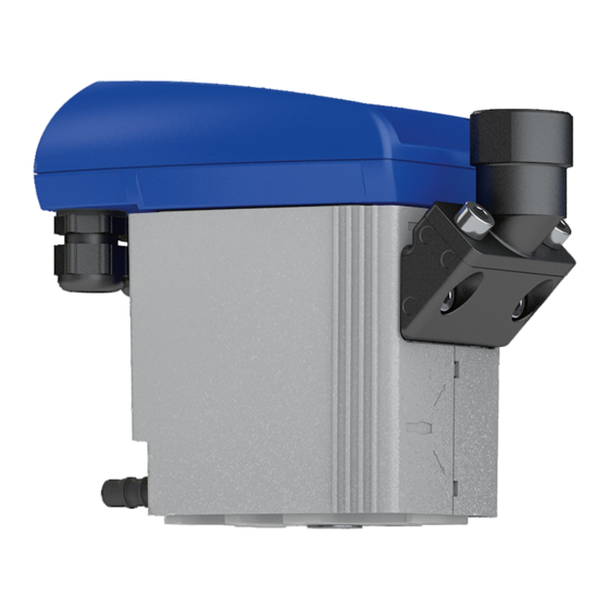
BEKOMAT ® 32iU Original installation and operation manual 3. Product information 3.1 Product overview Item Description / explanation Item Description / explanation Control unit, complete Condensate discharge Control panel Right cable gland Condensate inlet Left cable gland 14 | 68... -
Page 15: Exploded Drawing
Original installation and operation manual BEKOMAT 32iU ® 3.2 Exploded drawing Item Description / explanation Item Description / explanation Screw M3.5 x 10 [11] Service-Unit Top cover [12] O-ring 20 x 2 mm Moulded seal [13] Intermediate adapter Sensor board... -
Page 16: Function Description
BEKOMAT ® 32iU Original installation and operation manual 3.3 Function description Illustration Description / explanation The condensate flows via the condensate inlet [C] into the BEKOMAT and collects in the collecting tank [K]. ® The filling level in the collecting tank [K] is continuously monitored by a capacitive sensor in the sensor tube [L]. -
Page 17: Modbus Function
Original installation and operation manual BEKOMAT 32iU ® 3.4 Modbus function The BEKOMAT has an integrated Modbus which can be used to read out the operating parameters and device ® information. The BEKOMAT is operated using the client-server system with operating mode Modbus-RTU. -
Page 18: Read Input Registers (0X04)
BEKOMAT ® 32iU Original installation and operation manual 3.4.3.1 Read Input Registers (0x04) Modbus Contents Description / explanation Data type address 1116 Main Timer Hi-Word Operating hours counter [h] 1117 Main Timer Lo-Word 1102 Main Counter Hi-Word Counter for switching cycles... -
Page 19: Read Device Identification (0X2B / 0X0E)
Production: free 04/02/2018/08:25:44/01/01/01 ASCII BEKO material number 0x85 n.a. 0004046022 ASCII BEKOMAT ® 0x86 n.a. BEKO serial number BEKOMAT 0014345535 ASCII ® Customer material number, 0x87 n.a. ASCII optional * Legend: APP = application BBS = BEKO basic software CFG = Configuration 19 | 68... -
Page 20: Changing Interface Parameters
BEKOMAT ® 32iU Original installation and operation manual 3.4.3.3 Changing interface parameters INFORMATION BEKO TECHNOLOGIES configuration tools! BEKO TECHNOLOGIES recommends using the Software Integrator to change the interface parameters. The software can be downloaded from the BEKO TECHNOLOGIES homepage (see “1.1 Contact” on Page 5). -
Page 21: Error Messages
Original installation and operation manual BEKOMAT 32iU ® 3.4.3.4 Error messages Error code Error message Description / explanation ILLEGAL FUNCTION Function not implemented ILLEGAL DATA ADDRESS Requested address outside of the valid range ILLEGAL DATA VALUE Incorrect data SERVER DEVICE FAILURE Error occurred during inquiry that cannot be corrected 3.5 Type plate... -
Page 22: Scope Of Delivery
BEKOMAT ® 32iU Original installation and operation manual 3.6 Scope of delivery The table below shows the scope of delivery of the BEKOMAT ® Illustration Description / explanation BEKOMAT 32iU ® Original installation and operation manual Original Installations- und Betriebsanleitung BEKOMAT ®... -
Page 23: Technical Data
Original installation and operation manual BEKOMAT 32iU ® 4. Technical data 4.1 Operating parameters BEKOMAT 32iU ® Ambient relative humidity 10 … 80 %, without condensation 2000 m Maximum operating height 2187.23 yd 0.8 … 16 bar(ü) Minimum / maximum operating pressure 12 … 230 psi(g) +1 …... -
Page 24: Storage And Transportation Parameters
BEKOMAT ® 32iU Original installation and operation manual 4.2 Storage and transportation parameters BEKOMAT 32iU ® Minimum / maximum temperature, storage and +1 … +70 °C transportation +34 … +158 °F 4.3 Materials BEKOMAT 32iU ® Housing Aluminium and plastic, glass fibre reinforced Membrane 4.4 Dimensions 179 (7.05) G1/2 (NPT 1/2) 164,7 (6.48) -
Page 25: Screw Fastening Torques
Original installation and operation manual BEKOMAT 32iU ® 4.5 Screw fastening torques Item Description / explanation Fastening torques [Z1] Hose connection, condensate discharge 3 … 4 Nm (2.21 … 2.95 ft-lb) [Z2] Screws, condensate inlet 4 … 8 Nm (3 … 6 ft-lb) -
Page 26: Terminal Diagram
BEKOMAT ® 32iU Original installation and operation manual 4.7 Terminal diagram Illustration GND / 0V RS485 - B RS485 - A +24 V GND / 0V RS485 - B RS485 - A +24 V Modbus termination 26 | 68... -
Page 27: Transport And Storage
Original installation and operation manual BEKOMAT 32iU ® 5. Transport and storage WARNING Insufficient qualification! Insufficient qualification of the personnel carrying out work on the product and accessories can lead to accidents, personal injury and damage to property as well as impair operation. • The work on the product and accessories described below may only be executed and documented by skilled personnel - transport and storage. -
Page 28: Assembly
BEKOMAT ® 32iU Original installation and operation manual 6. Assembly 6.1 Warning notices DANGER Use of incorrect spare parts, accessories or materials! The use of incorrect spare parts, accessories or materials, as well as auxiliary and operating materials, may result in death or serious injury. Malfunction and device failure as well as material damage can occur. -
Page 29: Assembly Conditions
> 3 %. > 3% • Do not form water pockets. Drain line version • Do not use shut-off valves in the drain line. • Only connect the BEKOMAT to the drain ® line using a hose. 0 The hose compensates for assembly tolerances, vibrations and thermal expansion. •... - Page 30 BEKOMAT ® 32iU Original installation and operation manual Wrong Right Description / explanation Manifold design • The cross-section of the manifold must be at least equal to the sum of the individual cross- sections of the connected feed lines. •...
-
Page 31: Assembly Work
Original installation and operation manual BEKOMAT 32iU ® Wrong Right Description / explanation Ensure venting • If the slope in the inflow is not sufficient or there are other problems with the inflow, install a venting line. Discharge from pressurised pipes • Divert the flow of gas to provide a deflecting surface to discharge the fluid components in the gas. 6.3 Assembly work For assembly work to be carried out, the following prerequisites must be fulfilled and the preparatory tasks must have been completed. Prerequisites Tools Material Protective equipment •... - Page 32 BEKOMAT ® 32iU Original installation and operation manual Assembly work Illustration Description / explanation 1. Remove the plugs [18, 10] on the condensate inlet [C] and condensate discharge [D]. 2. Screw the enclosed hose connection [9] to the condensate discharge [D].
- Page 33 Original installation and operation manual BEKOMAT 32iU ® Assembly work Illustration Description / explanation Recommendation: To ensure easy maintenance of the product, install a shut- off valve [X2] in the condensate inlet line [X1]. 4. For the condensate inlet line [X1], apply sealant to the end of a pressure-resistant pipe and screw this in at the condensate inlet [C].
-
Page 34: Electrical Installation
BEKOMAT ® 32iU Original installation and operation manual 7. Electrical installation 7.1 Warning notices DANGER Use of incorrect spare parts, accessories or materials! The use of incorrect spare parts, accessories or materials, as well as auxiliary and operating materials, may result in death or serious injury. Malfunction and device failure as well as material damage can occur. -
Page 35: Connection Work
Original installation and operation manual BEKOMAT 32iU ® NOTE Electromagnetic interference! Electromagnetic faults caused by high-voltage cables, switchgears and high-frequency switching components, in particular speed-controlled and frequency-controlled drives (VSD/ VFD) can interfere with the operation of electronic devices and communication between electronic devices. • Mount electronic devices far away from high voltage cables, switching systems and high- frequency switching components. -
Page 36: Single Device Connection
BEKOMAT ® 32iU Original installation and operation manual 7.2.1 Single device connection Connection work - single device Illustration Description / explanation 1. Loosen the 3 screws [1]. 2. Lift the top cover [2]. 3. Unscrew the counter nut [6] from the right cable gland [E]. - Page 37 Original installation and operation manual BEKOMAT 32iU ® Connection work - single device Illustration Description / explanation Connection cable [X6] 8. Connect the connection cable [X6] according to the terminal diagram “4.7 Terminal diagram” on Page 9. Draw the connection cable [X6] taut.
-
Page 38: Connecting Multiple Modbus Devices (Series Connection)
BEKOMAT ® 32iU Original installation and operation manual 7.2.2 Connecting multiple Modbus devices (series connection) Connection work - series connection Illustration Description / explanation 1. Loosen the 3 screws [1]. 2. Lift the top cover [2]. 3. Unscrew the counter nuts [6] from the left cable gland [F] and right cable gland [E]. - Page 39 Original installation and operation manual BEKOMAT 32iU ® Connection work - series connection Illustration Description / explanation Connection cable [X6] 9. Connect connection cable [X5] and connection cable [X6] according to the terminal diagram “4.7 Terminal diagram” on Page 26.
-
Page 40: Commissioning
BEKOMAT ® 32iU Original installation and operation manual 8. Commissioning 8.1 Warning notices DANGER Operation outside the permissible limit range! Operation of the product and accessories outside the permissible limits and operating parameters, unauthorised intervention and modifications may result in death or serious injury. • Adhere to the limits and operating parameters specified on the type plate and in the manual. • Check whether the operating parameters have been amended or restricted by the use of accessories. -
Page 41: Commissioning Work
32iU ® 8.2 Commissioning work Illustration Description / explanation 1. Connect the voltage supply. 0 The BEKOMAT carries out the power-on self-test. ® 2. Slowly pressurise the system (e.g. by slowly opening the recommended shut-off valve [X2] in the condensate inlet line [X1]). -
Page 42: Operation
BEKOMAT ® 32iU Original installation and operation manual 9. Operation 9.1 Warning notices DANGER Operation outside the permissible limit range! Operation of the product and accessories outside the permissible limits and operating parameters, unauthorised intervention and modifications may result in death or serious injury. • Adhere to the limits and operating parameters specified on the type plate and in the manual. • Adhere to the assembly conditions and ambient conditions. -
Page 43: Operating States
Power Service Power Service • The green POWER LED is on (50 % brightness) while the solenoid valve is not cycling 0 The BEKOMAT switches to normal operation ® n = 20 Alarm Alarm Negative power-on self-test TEST... - Page 44 BEKOMAT ® 32iU Original installation and operation manual Illustration Description / explanation Discharge procedure (TEST button pressed briefly) Alarm • The red ALARM LED is off TEST Power Service • The green POWER LED is on (100 % brightness) while the solenoid valve is cycling n = ∞...
-
Page 45: Maintenance
Original installation and operation manual BEKOMAT 32iU ® 10. Maintenance 10.1 Warning notices DANGER Pressurised system! Danger of death or serious personal injury through contact with quickly or suddenly escaping fluids or through bursting system parts. • All maintenance and repair work on the system must be carried out in the depressurised state and with the system secured against unintentional pressurisation. -
Page 46: Maintenance Schedule
BEKOMAT ® 32iU Original installation and operation manual 10.2 Maintenance schedule Maintenance Interval Changing the Service-Unit After 2 x 8760 operating hours or 1 million switching cycles*; at least every 2 years Cleaning Annually Functional test Monthly Visual inspection Weekly... - Page 47 2. Press the TEST button briefly multiple times. TEST Power Service 0 The BEKOMAT is depressurised ® 0 The condensate remaining in the BEKOMAT ® drained 3. Release the control unit [A] by pressing the locking hook [X7]. 4. Remove the control unit [A]. 47 | 68...
- Page 48 BEKOMAT ® 32iU Original installation and operation manual Exchange work Illustration Description / explanation 5. Press the TEST button [A] on the control unit and hold it for at least 5 seconds. 0 The green POWER LED flashes Alarm 6. Once the green POWER LED is permanently lit, release TEST the TEST button.
- Page 49 Original installation and operation manual BEKOMAT 32iU ® Exchange work Illustration Description / explanation 11. Unscrew the two hexagon socket screws [14] in the connection adapter [13]. 12. First, pull the Service-Unit [11] away from the connection adapter [13] as shown and then lift it up and out of the rail.
- Page 50 BEKOMAT ® 32iU Original installation and operation manual Exchange work Illustration Description / explanation 19. Tighten the hexagon socket screws [14] with a torque of 4 … 8 Nm (3 … 6 ft-lb). 20. Fit the hose connection [9] with the hose [X3].
- Page 51 Original installation and operation manual BEKOMAT 32iU ® Exchange work Illustration Description / explanation 22. Check to confirm that the sealing mat [19] with contact springs [21] is clean, dry and free of foreign objects. 23. Insert the sensor of the control unit [A] into the sensor tube opening.
-
Page 52: Functional Test
0 The green POWER LED is illuminated (100 % brightness) 0 The valve opens and condensate is drained 10.3.3 Visual inspection During the visual inspection of the BEKOMAT , inspect all components for mechanical damage and corrosion. Replace ® damaged components immediately. -
Page 53: Cleaning
Local hygiene regulations! In addition to the cleaning instructions listed, any regionally applicable hygiene regulations must be observed. Preparatory tasks Proper shutdown of the BEKOMAT is completed. ® Cleaning work Spray mild detergent onto a cotton cloth or disposable tissue until it is damp (not wet). -
Page 54: Consumables, Accessories And Spare Parts
BEKOMAT ® 32iU Original installation and operation manual 11. Consumables, accessories and spare parts 11.1 Order information BEKO TECHNOLOGIES Service requires the following data for an inquiry or order: • Serial number (see type plate) • Material number and designation of the accessory or spare part •... -
Page 55: Spare Parts
Original installation and operation manual BEKOMAT 32iU ® 11.3 Spare parts Illustration Description / explanation Material no. Service-Unit 4023571 Design shell 4010167 Connection adapter 4010155 55 | 68... -
Page 56: Decommissioning
BEKOMAT ® 32iU Original installation and operation manual 12. Decommissioning 12.1 Warning notices DANGER Pressurised system! Danger of death or serious personal injury through contact with quickly or suddenly escaping fluids or through bursting system parts. • All work on the system must be carried out in the depressurised state and with the system secured against unintentional pressurisation. -
Page 57: Decommissioning Work
1. Interrupt the condensate feed via the condensate inlet line [X1] (e.g. by closing the recommended shut-off valve [X2]). 2. Press the TEST button briefly multiple times. 0 The BEKOMAT is depressurised ® Alarm TEST 0 The condensate remaining in the BEKOMAT ® Power Service drained 3. Disconnect the BEKOMAT from the voltage supply ® and switch off all power. -
Page 58: Dismantling
BEKOMAT ® 32iU Original installation and operation manual 13. Dismantling 13.1 Warning notices DANGER Pressurised system! Danger of death or serious personal injury through contact with quickly or suddenly escaping fluids or through bursting system parts. • All work on the system must be carried out in the depressurised state and with the system secured against unintentional pressurisation. - Page 59 Original installation and operation manual BEKOMAT 32iU ® Dismantling work Illustration Description / explanation 1. Remove the hose [X3] from the hose connection [9] and disassemble. 2. Remove the condensate inlet line [X1] and the recommended shut-off valve [X2] from the condensate inlet [C] and disassemble.
-
Page 60: Disposal
BEKOMAT ® 32iU Original installation and operation manual 14. Disposal 14.1 Warning notices NOTE Inappropriate disposal! Inappropriate disposal of parts, components, operating and auxiliary materials as well as cleaning media can cause environmental damage. • Dispose of all components, parts, operating and auxiliary materials as well as cleaning media professionally and in accordance with regional legal specifications and regulations. -
Page 61: Disposal Of Operational Materials And Components
Original installation and operation manual BEKOMAT 32iU ® 14.2 Disposal of operational materials and components Ensure the following prerequisites are met before disposal: Preparatory tasks The BEKOMAT has been decommissioned. ® The BEKOMAT is disassembled. ® The BEKOMAT is clean and free from all media residues. -
Page 62: Troubleshooting
BEKOMAT ® 32iU Original installation and operation manual 15. Troubleshooting Error or fault pattern Possible causes Troubleshooting n = ∞ Alarm TEST Power Service • Negative power-on self-test • Contact BEKO TECHNOLOGIES customer 0 The electronics unit is service (see “1.1 Contact” on Page 5) -
Page 63: Appendices
Original installation and operation manual BEKOMAT 32iU ® 16. Appendices 16.1 Approval certificates and declarations of conformity Symbol Description / explanation CE marking The CE marking indicates that a product fulfils all the EU directives applicable for this product and that basic safety and health requirements were met during manufacturing of the product. The product may be sold on the European market. -
Page 64: Declaration Of Conformity
BEKOMAT ® 32iU Original installation and operation manual 16.2 Declaration of Conformity 64 | 68... - Page 65 Product designation: Condensate drain Types: BEKOMAT 31U, 32U, 32UV, 33U, 33UV, 33U CO, 32iU, 32iUV, ® 33iU, 33iUV, 33iU CO Supply voltage versions: 95 … 240 VAC ±10% (50 … 60 Hz) / 100 … 125 VDC ±10% 24 …...
-
Page 66: Notes
BEKOMAT ® 32iU Original installation and operation manual 17. Notes 66 | 68... - Page 67 Original installation and operation manual BEKOMAT 32iU ® 67 | 68...
- Page 68 BEKO TECHNOLOGIES GmbH BEKO TECHNOLOGIES LTD. BEKO TECHNOLOGIES S.à.r.l. Im Taubental 7 Unit 11-12 Moons Park Zone Industrielle D - 41468 Neuss Burnt Meadow Road 1 Rue des Frères Rémy Tel. +49 2131 988 0 North Moons Moat F - 57200 Sarreguemines Fax +49 2131 988 900 Redditch, Worcs, B98 9PA Tél.
Need help?
Do you have a question about the 32iU and is the answer not in the manual?
Questions and answers