Table of Contents
Advertisement
Quick Links
Advertisement
Table of Contents

Related Manuals for Lumatek CONTROL PANEL PLUS 2.0


Summary of Contents for Lumatek CONTROL PANEL PLUS 2.0
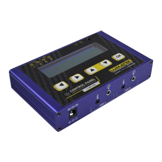
- Page 1 MANUAL CONTROL PANEL PLUS DUAL SIGNAL LIGHTING CONTROLLER FOR HID & LED...
-
Page 2: Table Of Contents
Setting pre-set Switch ON/OFF and light intensity times 5.2.6 Real time On/Off switching and adjusting light intensity 6. Controller LED indicator 7. LED failure indicator on electronic ballast 8. Lumatek controller troubleshooting 9. Maintenance and Repair 10. Environment and Disposal 11. Regulatory standards 12. Warranty... -
Page 3: Introduction
On/Off. Simply connect it to your Lumatek Controllable Fixtures or Ballasts and easily regulate your grow room environment. Thank you for purchasing the Lumatek Control Panel, we are sure you will be satisfied for years to come. Please read and understand this manual before installing and using the control panel as it contains all the information neces- sary to successfully install, use and maintain the product.Digital Control Panel... -
Page 4: Technical Specifications
BALLAST PER CONTROLLER CONTROLLABLE BALLAST TYPE 250W, 315W, 400W, 600W, 630W, 1000W CONTROLLABLE LED DRIVER TYPE All Lumatek controllable LED drivers 250W: 60%-110% (150W-275W) | 315W: 50%-100% (158W-315W) HID POWER DIMMING SCOPE 400W: 60%-110% (250W-440W) | 600W: 40%-110% (250W-660W) (1% INCREMENTS) -
Page 5: Safety Guidelines
Note! Each of the controller’s two channels (Zone A & Zone B) can control up to 200 Lumatek Control fixtures or ballasts. It is possible to use those channels to control fixtures in two separate rooms or to control up to 400 fixtures in one room. - Page 6 For LED: 1. Mount the fixtures as per your lighting plan. Interconnect them as described in the manual for the fixture, using the LED control cable supplied with the controller and a control link cable purchased separately for each additional fixture to be daisy-chain connected in series. CONNECT CONTROLLER CABLE TO SIGNAL IN Using LED control link cable, connect LED fixture 1 ‘Signal Out’...
-
Page 7: Setting Up The Controller
Warning! The controller may only be connected to compatible Lumatek controllable LED fixtures and ballasts. Find a suitable place for the temperature sensor and the controller. Hang the sensor between the plants at average canopy height and preferably not against the wall. Do not position in direct airflow or light. If you are using another climate control system, hang temp sensor close to the sensor of that system. -
Page 8: System Settings
2. System Settings ‘To set temperature scale and power output unit of measurement: Press [OK] and then [>] to ‘System Settings’ and [OK] to enter Press [<]or[>] to ‘Temp’ and [^]or[v] to toggle between ‘C’ (Celsius) or ‘F’ (Faren- heit). Press [OK] to save. Press [<]or[>] to ‘Power’;... -
Page 9: Setting Pre-Set Switch On/Off And Light Intensity Times
In ZONE A Press [<]or[>] to Power and [^]or[v] to select required power output and Press [OK] to save. Setting simulated sun rise and set period: To allow crops to adjust to either a lights-On period or lights-Off period, a sunrise and sunset period may be set. -
Page 10: Real Time On/Off Switching And Adjusting Light Intensity
Press [<]or[>] to Hour and Minute settings and [^]or[v] to set time in hours and minutes and [OK] to save. Press [>] to Power setting and [^]or[v] to set power output and [OK] to save. To pre-set switch Off; set Power to 0%. 6. -
Page 11: Lumatek Controller Troubleshooting
Note! To reset ballast; disconnect from mains and reconnect after 30 seconds Warning! When replacing a lamp, always switch Off ballast first by removing plug from power supply. Never switch off lamp by removing lamp cable from a live ballast. 8. LUMATEK CONTROLLER TROUBLESHOOTING FAULT INSPECTION METHOD TROUBLESHOOTING... -
Page 12: Maintenance And Repair
If the product shows any defects within this period and that defect is not due to user error or improper use Lumatek Ltd shall, at its discretion, either replace or repair the product using suitable new or reconditioned products or parts. - Page 13 SET SIGNAL PROTOCOL SET SIGNAL PROTOCOL INCREASE OR INCREASE OR RIGHT SHIFT RIGHT SHIFT DECREASE DECREASE PARAMETERS PARAMETERS PAGE UP OR PAGE UP OR OK AND SAVE OK AND SAVE PAGE DOWN PAGE DOWN ZONE B LIGHT ZONE A LIGHT ZONE B LIGHT POWER ADAPTOR ZONE A LIGHT...
Need help?
Do you have a question about the CONTROL PANEL PLUS 2.0 and is the answer not in the manual?
Questions and answers