Advertisement
Quick Links
Advertisement

Related Manuals for Patriot Patriot 3.8m Commercial Antenna King Post Mount


Summary of Contents for Patriot Patriot 3.8m Commercial Antenna King Post Mount
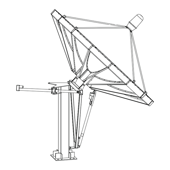
- Page 1 3.8m Commercial Antenna King Post Mount...
- Page 2 LIMITED TWELVE (12) MONTH WARRANTY This PATRIOT ANTENNA equipment is warranted to be free from defects in material and workmanship un- der normal use and service. PATRIOT ANTENNA shall repair or replace defective equipment, at no charge, or at its option, refund the purchase price, if the equipment is returned to PATRIOT ANTENNA not more than twelve (12) months after shipment.
- Page 3 INSTALLATION OF THIS PRODUCT SHOULD BE PERFORMED ONLY BY A PROFESSIONAL INSTALLER AND IS NOT RECOMMENDED FOR CONSUMER D.I.Y. (DO-IT-YOURSELF) INSTALLATIONS. Installation of this product near power lines is dangerous. For your own safety, follow these important safety rules. 1. Perform as many functions as possible on the ground. 2.
-
Page 4: Unpacking And Inspection
Introduction Thank you for purching your Patriot Commercial Antenna. We trust that you will fi nd this to be a well designed product that will proved many years of reliable service. Please read this manual thoroughly before beginning assembly. For best results in the assembly process, perform each step in the same sequence as listed in this manual. - Page 5 ITEM # PART# 231106 238004 238005 238006 238007W 238009 238020 238108 PRT-KING450 4M38009 4M38004 PG 6 245002 PG 7 245020 PG 7 TS-36BRC PG 8 PRT-MEB001 PG 8 DESCRIPTION PLATE, C-BAND 3.1/3.8/405 ASSY, 3.8 COMMON HUB OUT BRD SKIRT, 3.8 PRIME RADIAL BEAM 3.8 PRIME PETAL, 3.8 PRIME STRUT, 3.8 PRIME STRD FD...
- Page 7 SECTION A-A 24.00D 1/16" NGULAR: 2 2 .062" 2.031" 2.015"2...
-
Page 8: Antenna Placement
Antenna Placement: The AzEl Fixed King Post mount is designed to have a total arc coverage of 132 degrees. The pad bolts must be placed in the concrete to allow coverage of the desired portion of the satellite arc. Please consult a satellite chart, software program or a qualified consultant for compass setting to point the king post bolt template. - Page 9 Mount Assembly- Fixed 1. Place the King Post assembly onto the foundation sliding the bottom plate on to the threaded studs point- ing the “A-frame” assembly of the mount in the desired direction- south in the northern hemisphere, north in the southern hemisphere.
- Page 10 Mount Assembly- Motorized 1. Set King Post to foundation as instructed on previous page. 2. Assemble the azimuth actuator to the main post and A-frame locking it into a steady position so the Hub assembly can be safely placed. 3. With 2 helpers place the hub assembly in the zenith (bird bath) position on top of the King Post A-frame as shown using the preassembled hardware in place on the A-frame.
-
Page 11: Reflector Assembly
Reflector Assembly 4M38004 (ANGLE, 3.8 HUB) to hub as pictured below 1. Install 1. Install the Radial Beams to the Hub Angles which are pre-installed to the hub, using hard- Make sure the cut corner is towards the BOTTOM of the hub assembly. ware labeled- Radial Beam to Hub. - Page 12 5. Set in place 2 Panels into the Radial Beams. The Radial Beam will be between the fl ange of each Panel (see below). Using 3 tapered alignment tools- 2 in the outermost holes, and 1 in the center hole to align the holes in the panels and radial beam, install the hardware in the remaining holes (from kit labeled- Petal to Radial Beam) starting with the hole closest to the hub.
- Page 13 Feed Plate Feed Support Assembly- Standard1. Place the Feed Struts in place with the Feed C-Band PT# COVR STD FOR: PT# COVR-SVY FOR:...
- Page 14 With a helper place the center plate in place in the center of the opening of the panels using hardware from Center Plate pack. From behind place the back brace through the hub center across the hub opening. Tighten the nut on the bolt being careful not to overtighten which could crush the petals.
- Page 15 Grounding Grounding Antenna Feed Cables 1. Ground antenna feed cables in accordance with current National Electric code and local elec- tric codes. The illustration shows a typical grounding method. Clamps that provide a solid connection between ground wire and a ground source should be used. Grounding Non-Penetrating Mount Frame (if applicable)
- Page 16 Specifications Electrical Gain Noise Temp. (20 degree elev) (30 degree elev) 3dB Beamwidth Avg 1st Side Lobe Cross Polarization VSWR (max) 2 Degree discrimination Mechanical Antenna Size Focal Distance Operational Wind Survival Wind Operational Temp Rain Weight C-Band Ku-Band 41.5 dBi 50.5dBi 1.3Deg .45Deg...
Need help?
Do you have a question about the Patriot 3.8m Commercial Antenna King Post Mount and is the answer not in the manual?
Questions and answers