Advertisement
Quick Links
Advertisement

Subscribe to Our Youtube Channel
Related Manuals for Patriot PRT-240M NAV


Summary of Contents for Patriot PRT-240M NAV
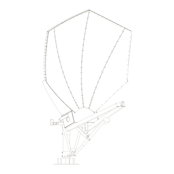
- Page 1 2.4m N Offset Receive 2.4m Navigator Offset Antenna Transmit Receive only and Transmit-Receive...
- Page 2 PATRIOT ANTENNA shall repair or replace defective equipment, at no charge, or at its option, refund the purchase price, if the equipment is returned to PATRIOT ANTENNA not more than twelve (12) months after shipment. Removal or reinstallation of equipment and its transportation shall not be...
- Page 3 Thank you for purchasing your Patriot Commercial Antenna. We trust that you will fi nd this to be a well designed product that will provide many years of reliable service. This manual will help you to know the tools and proper installation of the product. Please check, read and understand the content of this manual before beginning your antenna installation.
- Page 4 Item# Descripition Part# Rev# PRT-240M NAV PANEL,2.4 OFFSET B RIGHT 224099 PANEL,2.4 OFFSET A LEFT 224100 PANEL,2.4 OFFSET A RIGHT 224101 PANEL,2.4 OFFSET B LEFT 224102 ASSY, RADIAL BEAM 2.4 OFFSET A 224103 ASSY, RADIAL BEAM 2.4 OFFSET B 224106 ASSY, RADIAL BEAM 2.4 OFFSET C...
- Page 5 In-Ground Mast Foundation 6-5/8in. O.D. Pipe 42” Grade Level 48” min. 60” Anti-Twist Weldment 24” Diam. Foundation Requirements & Specifications: • Steel Mast: 6” Schedule 80, L=90”; 6 5/8” O.D. • Concrete: 3000 psi at 28 days, poured against undistrurbed soil (Allow concrete 24 hour set time before installation of antenna) •...
- Page 6 Mast Pipe(optional) with Bolt & Template Kit #4 Rebar in all concrete pad surfaces 6 5/8” O.D. Steel Pipe 42” Above Support 42” gussets Base Plate 18”x18”x1/2” 4 Anchor Bolts 4 Typ 1 1/4” 1 1/4” Diam. Diam.x24” The Optional Kit Includes: Schedule 80 6”...
-
Page 7: Mount Assembly
Mount Assembly 1. Slide 295031G (NAV BTM COUPLER), and then 295032G (NAV TOP COUPLER)over the mast pipe as shown. Do not tighten the set bolts at this time. 2. Attach 295047G(NAV YOKE) to 295032G (NAV TOP COUPLER) and 295031G (NAV BTM COUPLER) using pre-installed ¾ shoulder bolts and 5/8 nuts. 3. -
Page 8: Reflector Assembly
Reflector Assembly 4M45004 (ANGLE,4.5 HUB) 1. Fasten to 224133 (HUB, 2.4 MOTORIZED) as shown, using hardware from Hardware Pack#3HP240002. (Make sure that the angle cut is pointing TOWARDS back of hub as pictured) 2. Repeat step till all 5 angles are attached. 224133 4M45004 (HUB, 2.4 MOTORIZED) - Page 9 Reflector Assembly (continued) Reflector Assembly (continued) 2. Attach 22433 (Hub, 2.4 motorized) to 295047G (Assem, 1.8m nav Yoke Galv.) to yoke as 2. Attach 22433 (Hub, 2.4 motorized) to 295047G (Assem, 1.8m nav Yoke Galv.) to yoke as pictured below. (This will require two people to lift Hub Assem into place use pre attached pictured below.
- Page 10 Radial Beam Assembly 1) Attach 224109 (ASSY, RADIAL BEAM 2.4 OFFSET C) to the INSIDE of 4M45004 (ANGLE,4.5 HUB) (as pictured) to insure proper beam focus, using one 3/8 washer, one 5/16 lock washer, and one 5/16 nut per 3/8 shoulder bolt. 2) Repeat step on on next radial beam 224106 (ASSY, RADIAL BEAM 2.4 OFFSET B) till all...
- Page 11 Panel Assembly 224102 (PANEL,2.4 OFFSET B LEFT) 1. Attach using 1/4-20 Button Head panel Screw from harware bag 3HP240001. (Leave screws loose at this time) 2. Attach all other panels in the same manor as described in step one leaving all screws loose at this time. 224099 (PANEL,2.4 OFFSET B RIGHT)
- Page 12 Panel Assembly (cont.) 3. Attach 224128 (ASSEMBLY, 2.4OFFSET CURFING SHORT) to 224099 (PANEL,2.4 OFFSET B RIGHT), and the other to 224102 (PANEL,2.4 OFFSET B LEFT) using same screws from hardware pack 3HP240001. Attach 224129 (ASSEMBLY, 2.4OFFSET CURFING LONG ) to 224101 (PANEL,2.4 OFFSET A RIGHT), and the other to 224100 (PANEL,2.4 OFFSET A LEFT) using same screws from hardware pack 3HP240001.
- Page 13 Feed Boom and Feed Assembly 1.Attach224112 (TUBE,SUPPORT 2.4 OFFSET FEED) to bottom side of Hub Leave all hardware using 1/2 hardware with bolt and washer inside of hub. loose at this time 224112 2. Repeat step one to attach other Leave all hardware loose at this time 224131 (SHIM, 2.4M...
- Page 14 Feed Adjustment (Polarity tuning) 1. Adjust the Feed to the appropriate skew angle using the provided scale reference. Polarity Scale NOTE: Refer to the chart on back for polarization Reading Points angle. Elevation and polarity are both dependent on site azimuth and the difference between satellite and site longitude.
- Page 16 Operational Temp -40 to 140 F Rain Operational = 1/2in./hr Survival = 3in./hr 1 in. Radial -or- 1/2 in. + 60mph wind Pole Size 6-5/8” OD PATRIOT ANTENNA SYSTEMS 704 NORTH CLARK STREET ALBION, MICHIGAN 49224 USA WWW.SEPATRIOT.COM 2MFCC-240NVDASO REV001...
Need help?
Do you have a question about the PRT-240M NAV and is the answer not in the manual?
Questions and answers