Advertisement
Quick Links
Advertisement

Related Manuals for Patriot 1.0m


Summary of Contents for Patriot 1.0m
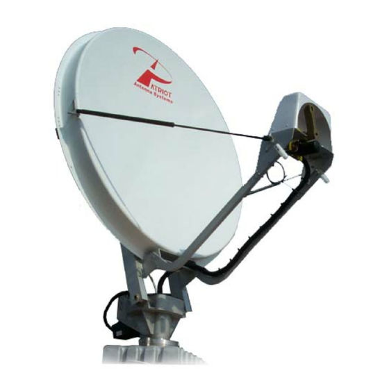
- Page 1 1.0m-1.2m Dual Optic Offset Antenna Transmit-Receive...
- Page 2 PATRIOT ANTENNA shall repair or replace defective equipment, at no charge, or at its option, refund the purchase price, if the equipment is returned to PATRIOT ANTENNA not more than twelve (12) months after shipment. Removal or reinstallation of equipment and its transportation shall not be...
- Page 3 Assembling dish antennas on windy days can be dangerous. Because of the antenna surface, even slight winds create strong forces. For example, a 1.0m antenna facing a wind of 32 km/h (20 mph) can undergo forces of 269 N (60 lbs.). Be prepared to safely handle these forces at unexpected moments. Do not at- tempt to assemble, move or mount dish on windy days or serious, even fatal accidents may occur.
- Page 4 Introduction Thank you for purching your Patriot Commercial Antenna. We trust that you will fi nd this to be a well designed product that will proved many years of reliable service. Please read this manual thoroughly before beginning assembly. For best results in the assembly process, perform each step in the same sequence as listed in this manual.
- Page 5 CLEVIS, UPPER ELEV BIG 210083G THRD ROD,1/2NF X 13”FINE 3HT08130FS SEE PG 9 SPACER, .25L x1.25od x .312 id 3HM11100 TUBE, 1.0m DUAL OPTIC FEED 210005 TUBE, 1.2m DUAL OPTIC FEED 212005 ASSY, 1.0m BACK STRUCT. 210002G ASSY, 1.2m BACK STRUCT 212002G REFLECTOR, 1..0M GRAY...
- Page 7 Non-Penetrating Mount (optional) 1. Assemble the Non-Penetrating mount per the supplied instructions to provide the mast for the mount installation. 2. Refer to the ballast chart for the required ballast to be placed in the Non-Pen Ballast Trays. NOTE: Higher elevation angles can use less ballast. If there are any possible future elevation adjustments that could result in a lower elevation angle use the 22 deg elevation angle from the chart for the ballast requirement! 100cm Ballast Chart...
-
Page 8: Az-El Mount Assembly
Az-El Mount Assembly 1. Using the hardware illustrated, as- semble the Pipe brackets, Azimuth bracket, and Clevis bracket as shown. Azimuth Bracket Clevis Pipe Bracket... - Page 9 Back Structure Assembly 1. Attach Refl ector to Back Structure as pictured below. 2. Insert plastic cap into end as pictured. NOTE: Use the two spacers where shown as pictured below ONLY on 1.0m Antenna. 210002G 2100-0002 ASSY, 1.0m BACK STRUCT.
-
Page 10: Mount Assembly
Mount Assembly 1. Attach the Antenna-Back Structure Assy to the Azimuth Bracket using the illustrated hardware. 2. Add the Elevation adjustment hardware and Upper Clevis using the hardware shown. 3HT09130FS THRD ROD, 1/2 NF x 13” 1/2” WASHER ON BOTH SIDES 3HN050125CNFHXS OF THE CLEVIS NUT, 1/2 NF COUPLING... -
Page 11: Feed Support Assembly
Feed Support Assembly 1. Bolt the Feed Support Tube to the Back Structure using 2- 3/8 bolts, washers(2 per) and nuts. 210005 TUBE, 1.0m D.O. FEED 202005 TUBE, 1.2m D.O. FEED INSTALL CAP ON THIS END 2. Assemble the Sub Reflector to the Feed Support Tube using 4- 1/4x2-1/2 bolts, washers. - Page 12 Grounding Coaxial Cable (to LNB) Ground Block Grounding Antenna Feed Cables NEC Section 810 1. Ground antenna feed cables in accordance with current National Electric code and local elec- tric codes. The illustration shows a typical grounding method. Ground Wire Clamps that provide a solid connection between NEC Section 810 ground wire and a ground source should be used.
- Page 13 Ku-Band Ku-Band 1.0 m Type-Approved 1.0 m Type-Approved Intelsat Type-Approval #IA084A00 Tx/Rx Antenna Systems Tx/Rx Antenna Systems Ka-Band Receive Transmit Receive Transmit Polarity Linear Linear Circular Circular Frequency 18.2 - 21.2 GHz 27.5 - 31 GHz 19.7-20.2 GHz 29.5-30 GHz Feed - 2 - Port Xpol Return Loss 17.7 dB typ...
- Page 14 1.2 m 1.2 m Eutelsat Type Approval # EA-A020 Tx/Rx Antenna Systems Tx/Rx Antenna Systems Intelsat Type Approval # IA083A00 C-Band Linear C-Band Circular Ku-Band Ku-Band Linear Transmit Receive Transmit Receive Transmit Frequency 5.7-6.725 GHz 3.625-4.2 GHz 5.85-6.425 GHz Frequency 10.7 - 12.75 GHz 13.75 - 14.5 GHz Feed - 2 Port Xpol...
- Page 15 Notes:...
- Page 16 Notes:...
- Page 17 Feed Adjustment (Polarity tuning) 1. Adjust the Feed to the appropriate skew angle using the provided scale reference. Polarity Scale NOTE: Refer to the chart on back for polarization Reading Points angle. Elevation and polarity are both dependent on site azimuth and the difference between satellite and site longitude.
- Page 19 Toll Free 1-800-470-3510 Equipment From The Industry’s Lead- ing Satellite Equipment Manufacturer’s Available Together - In One Place... We are Cal-Amp’s LARGEST STOCKING DISTRIBUTOR! No Long Lead Times... No Drop Ship Fees... High Inventory... Great Prices... i n g : W e A l s o O f f e r P r o d u c t s f r o m t h e f o l l o w Complete line of Quality Feedhorns, Durable Snow Covers for Commercial...
-
Page 20: Specifications
Rx Gain dBi (Midband) 44.60 - 46.00 40.30 - 41.80 Efficiency Side Lobes ITU-580-5 Cross Polarization (on axis) 35dB Mechanical Antenna Size 1.0m (39.4”) 1.2m (47.3”) Offset Angle 22 degrees 0.635 Operational Wind 50mph Survival Wind 125mph Operational Temp -40 to 140 F...
Need help?
Do you have a question about the 1.0m and is the answer not in the manual?
Questions and answers