Advertisement
Advertisement
Table of Contents

Related Manuals for VINKA amslod DC40


Summary of Contents for VINKA amslod DC40
- Page 1 DC40 VINKA Display User Manual VERSION...
-
Page 2: Product Name And Model
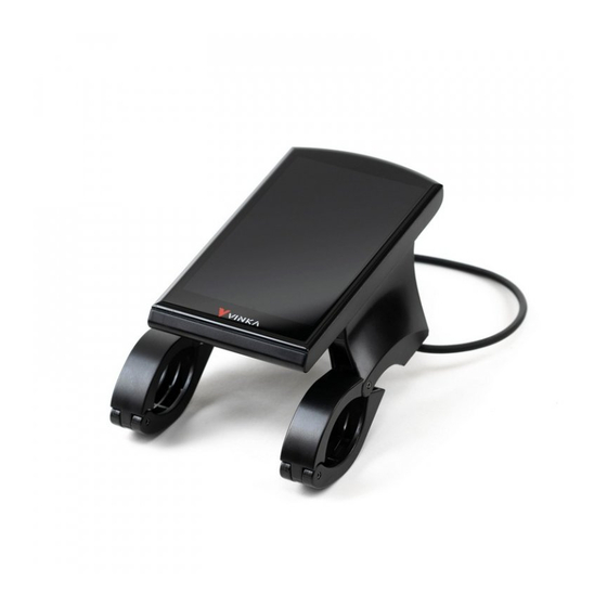
Product name and model Name: Intelligent colored LCD for E-bike Model: KD986 Specifications ● 36V/48V Power Supply ● Rated working current: 50mA ● The maximum working current: 200mA ● Off-state leakage current: <1μA ● Operating temperature: -20℃~ 60℃ ● Storage temperature: -30℃~ 70℃ Appearance and Size ◆... -
Page 3: Function Summary
◆ Remote control appearance and dimensional drawing (unit: mm) Function Summary DC40 can provide a lot of functions to fit the Users needs. The indicating contents are as follows: ● Battery SOC indication ● Motor Power indication ● Assist-level indication and selection ●... -
Page 4: General Operation
General Operation ◆ Switching the E-bike System On/Off Briefly press the power button to switch on the E-bike system and start to power up the controller. To hold the power button for 1 s again, the E-bike system will be switched off .The E-bike system no longer uses the battery power. - Page 5 ◆Switching Push-assistance Mode On/Off To activate the push-assistance function, first short press i button and keep holding the “-” button. After 1 s, The E-bike’s drive is activated at a uniform speed of 6 Km/h while the screen displays “ ”.
- Page 6 ◆Assist Level Selection Briefly press "+" or "-" button to switch between assistance levels so as to change the motor output power, The default assistance level ranges from level “0” to level “5”, The output power is zero on Level “0”. Level “1” is the minimum power. Level “5” is the maximum power.
- Page 7 ◆Motor Power Indicator The power of the motor can be read via below interface, left yellow segments. Motor Power Indication Interface ◆Error Code Indication The components of the E-bike system are continuously and automatically monitored. When an error is detected, the respective error code is indicated in text indication area. Here is the detail message of the error code in Attached list 1.
- Page 8 Settings Hold the On/Off button to switch on the display. To access Settings page, hold both the “i” button and the “-” button simultaneously for more than 1 s. Setting interface ▉ All the Settings operations are done to a stationary E-bike with no speed. ◆...
- Page 9 ◆Walk speed Walk Speed represents walk assistance speed settings. press the “+” button or the “-” button to choose the desired walk speed. Press “I” button to save a changed setting. “ Walk speed” interface ◆ Speed Limitation Settings Speed Limitation represents the limited speed settings. When the current speed is faster than speed limit, the E-bike system will be switched off automatically.
- Page 10 ◆ LCD brightness LCD brightness represents backlight brightness settings. Level 5 is the highest brightness. Level 1 is the lowest brightness. To change the backlight brightness, press the “+” button or the “-” button to choose the desired level. To store a changed setting, briefly press the “i” button to confirm. “LCD brightness”...
- Page 11 ◆Assist indicator Assist Indicator represents assist level settings。 Type C: level 0~5, 6 assist levels, press +/- to change the assist level. “Assist indicator” interface ◆GSGI function: GSGI means gear shifting calibrations, mainly for CALIB FD and CALIB RDIGH GSGI gear shifting sensor can identify gear position and provide shift reminder to ensure that riders have efficient and comfortable riding conditions.
- Page 12 ◆About: It is for checking the display and motor information, such as the display serial number, voltage type ect.. “About” interface...
-
Page 13: Quality Assurance And Warranty Scope
Quality Assurance and Warranty Scope Ⅰ Warranty (1)The warranty will be valid only for products used in normal usage conditions. (2)The warranty is valid for 24 months after the shipment or delivery to customers Ⅱ The following cases do not belong to our warranty scope. 1. - Page 14 Attached list 1: Error code definition Error code Definition Torque Zero Error Torque Out Range Torque Sensor Fault Gear Sensor Error Speed Sensor Error Cadence Error PCB Over-Temp Warning PCB Over-Temp Error PCB Sensor Fault Motor Over-Temp Warning Motor Over-Temp Error Flash Error Communication Lost LORA Communication Lost...
Need help?
Do you have a question about the amslod DC40 and is the answer not in the manual?
Questions and answers
Wie kann ich den Tageskilometer (Trip) auf null stellen?
Wie stelle ich den Tageskilometerzähler zurück?