
Related Manuals for microSYST MS8111PWM3S


Summary of Contents for microSYST MS8111PWM3S
- Page 1 COMPETENCE IN MEASUREMENT UNIVERSAL DUAL CHANNEL PROGRAMMABLE CONTROLLER WITH TIMER OR ALARM MS8111PWM3S v1.2 USER MANUAL PLOVDIV 2018 Редакция документ 2018-11-02...
- Page 2 Редакция документ 2018-11-02...
- Page 3 • Difference from the previous version of the software : - 0.1s format is added in timer modes. The controller has 5 outputs / three discrete and two analog / • Discrete outputs K1 and K2 are control outputs of temperature controllers.
-
Page 4: Table Of Contents
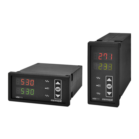
Programmable timer or alarm Analog outputs Display: 2 x4 digits LED MS8111PWM3S is used for baked bread, bakery and confectionery, ceramics, rubber production, hardening of metals, HVAC, greenhouses and others. 1. DESIGNATION The Microprocessor Two Channel Controller MS8111PWM3S is designed to control two processes simultaneously using a proportional or positional control law. -
Page 5: Order Code
2. ORDER CODE MS8111PWM3S - x.x.x.x.x.x.x.x.x.x Housing Code Code М1 - box Ip5496x48x125 - Alarm horizontal panel - Timer 1М - box Ip5496x48x125 - not connected vertical panel Input Channel 1(C1) Input Channel 2(C2) code C1 C2 Code 1 21 0.0 100,0 °C... -
Page 6: Technical Data
3. TECHNICAL DATA Analog inputs Linear current 0 ÷ 20 mA DC; 4 ÷ 20 mA DC Linear Voltage 0 ÷ 1 (10) V DC Thermoresistor Pt 100, P1000 EN 60751 Thermocouple J, K, EN 60584 Other By order 0.15% of the range Measurement accuracy Digital inputs Optically isolated- active level GND ISO,... -
Page 7: Operation
4. OPERATION Display Basic parameters used in the device: Set Point Zоn proportional zone or hysteresis in ON/OFF control Zone - Process variable - input parameter Alarm Hi - upper alarm limit ALО Alarm Lo - lower alarm limit In operational mode, the upper display shows the value of Channel 1, while the lower display shows the value of Channel 2. -
Page 8: Timer - Modes Of Operation
TIMER - MODES OF OPERATION 4.3. Permitted by the SrEG parameter from the Hidden System Parameters section. The timer section can work independently of the rest of the controller (from the measured value) by starting / stopping with buttons or on the pulse front at the "Start timer" input or it works depending on the measured value as the timer starts when the assigned value is reached(selected by the SrEG parameter). -
Page 9: Timer - Edit Time
Change the set time display). - Editing the value is done vie the DOWN and UP buttons, while confirmation - with the SET button. 5. FRONT AND BACK PANEL. TERMINALS AO1 GND +12V DIG1 Multyfunctional process controller MS8111 microsyst Pt100 Редакция документ 2018-11-02... -
Page 10: Analog Inputs Connections
6. ANALOG INPUTS CONNECTIONS For the sake of good functioning, it's important that the probes are located on a suitable place in the environment, in which the temperature regulation will take place. Resistive sensors connection (Pt100 or others) The sensors can be connected via a two-wire or three-wire line. The connection of two-wire sensors to a three-wire line follows the diagram shown in FIG. -
Page 11: Transmitters Connection
Transmitters connection Transmitters with two-wire connection 6.3.1. The power to the transmitters is provided by the unit. Fig. 4 * The device provides unstable voltage from 11.5V to 14.5V / max 50mA 6.3.2. Transmitter with own power supply U power U захр. -
Page 12: Connection To Start The Timer
7. CONNECTION TO START THE TIMER external button (start by front) Used when the timer operates independently of the measured input variables Start Timer – кл.26 GND ISO – кл.23 external switch (start by level) Used when the timer operates depending of the measured input variables 8. -
Page 13: System Parameters
9. SYSTEM PARAMETERS The system parameter programming mode is accessed by pressing buttons UP and DOWN simultaneously for more than 5 seconds. In the mode, the parameter's name is shown on the lower display. With buttons DOWN and UP the desired parameter is selected, and with SET button, on the upper display, the parameter's value is displayed. -
Page 14: Consumer Setting Of Offset On Analog Channels
10. CONSUMER SETTING OF OFFSET ON ANALOG CHANNELS In this mode, users can freely enter a programmable value, which will always be added to the measurement ("offset"). This is used when there's a discrepancy between the value displayed by the device and measured with another reference instrument. To authorize the user offset of the readings of both channels, it is necessary to power on the device while the DOWN button is pressed. -
Page 15: Hidden System Parameters
12. HIDDEN SYSTEM PARAMETERS USED ONLY BY SERVICE SPECIALIST! WRONG SETTINGS MAY LEAD TO THE INCORRECT FUNCTION OF THE DEVICE! Hidden system parameters are “visible’’ only until the next shut down. To access hidden system parameters, it’s needed to feed the power supply while holding and pressing the UP button. - Page 16 0 - K3 - ALARM timer operates independently of the measured input variables К3 – TIMER – mode 1 in seconds 129 – mode 1 in minutes 130 – mode 2 in seconds 131 – mode 2 in minutes 132 – mode 1 in seconds x 0.1 133- mode 2 in seconds x 0.1...
- Page 17 Date of Order Service Type of repairs done transmiss out the receipt number repair Seller:....Buyer:....4, Murgash str., Plovdiv city, Bulgaria, 4000 Тел.: (+359 32) 642 519, 640 446 факс: (+359 32) 640 446 www.microsyst.net e-mail: info@microsyst.net Редакция документ 2018-11-02...
Need help?
Do you have a question about the MS8111PWM3S and is the answer not in the manual?
Questions and answers