
Subscribe to Our Youtube Channel
Related Manuals for microSYST MS8357


Summary of Contents for microSYST MS8357
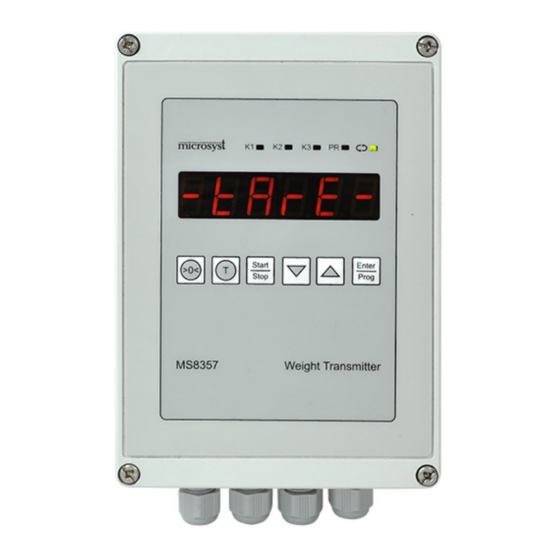
- Page 1 COMPETENCE IN MEASUREMENT WEIGHT BATCHING CONTROLLER with Analog Output and MODBUS RTU communication MS8357 V 2.1 TECHNICAL DESCRIPTION USER MANUAL PLOVDIV 2015 Document revision 2015-08-17...
-
Page 2: Order Code
OPERATING GUIDE SYSTEM PARAMETERS OF THE REGULATOR ACTIONS AGAINST INTERFERENCE COMMUNICATION - MODBUS RTU ORDER CODE MS8357 - x.x.x.x.x.x.x.x Sensor supply / sensitivity Display color 1 - 5 VDC : 1 … 7 mV / V 1 - Red 2 - Other... - Page 3 ● IV. DESIGNATION MS8357 is suitable for including in dosing or batching systems by weight method. The input signal is formed by bridge weight sensor which is supplied by the device. The sensitivity and the power supply of the sensor are hardware fixed and have to be specified in the order code.
-
Page 4: Technical Data
V. TECHNICAL DATA Analog input from bridge weight sensor - power supply / sensitivity of the 5 V D / 1 ÷ 7 mV/ V sensor ........(other) - measurement accuracy 0.003% - temperature stability 5 ppm/ °C - conversion time without software According to the configuration of order code filter: and from SYST/rS485/bit6 menu:... - Page 5 FRONT AND BACK PANEL. TERMINAL AND ELECTRICAL CONNECTION 6.1. Connecting the Power Supply – by ORDER CODE Incorrect power supply causes serious damage !!! 6.2. Connecting of the Sensors The unit allows connection of up to 4 weight sensors. ● In 4-wire connection, the respective positive and negative terminals of the "Exc"...
-
Page 6: Operating Modes
6.2. Connecting of the Analog Output Analog output is one such type is configured in the Order Code ● 6.3. Connecting of the Digital Input 6.4. Connecting of the Digital Outputs Discrete outputs are identical and are of two types - relays or isolated open collector. Relay outputs have a common contacts and transistor outputs are with common emitters. - Page 7 Through ‘Config’ parameter is selected one of the two possible schemes of action: MODE А – Dispenser/ Batcher weight MODE А dose3 dose2 dose1 time output K3 Start tOff Declines in the graph are eventual interference or vibrations. If the measured value has ●...
- Page 8 MODE B – Comparator / Stage controller /: MODE B dose3 dose2 dose1 Declines in the graph are eventual interference or vibrations. Above certain set-point the ● respective output become active and it become inactive if the measured value is below the set-point.
- Page 9 8.9. SCREEN MENUS AND BUTTONS FUNCTION Button Function By pressing the button to change the on-screen menus in the following sequence : - Zero – Display the tare value - Count – Number of doses - Call – Calibration mode – it can be hidden - Prog –...
-
Page 10: Error Message
8.5. CALIBRATION - Call Before calibration the device has to be tared. Reference weight has to be placed. Allow to establish the value of the display. Enters “CALIBRATION” mode with button “Enter/Prog” . Use the arrows to correct the displayed value under placed reference weight. ... - Page 11 IX. SYSTEM PARAMETERS OF THE CONTROLLER Available when button Enter/Prog is pressed after power until inscription „Tune“ appears on the ● display. After releasing the button “SYSt” appears on the display. After pressing the button „Enter/Prog” parameters from the following table appear on the display: Parameter Function Value...
- Page 12 “ConFiG” - Configuration word - sum of the numbers from chosen options have to be entered (i.е. Sum of 8 numbers) * Bit 0 Inversion of К1 output ** Bit 1 Inversion of К2 output Bit 2 Inversion of К3 output Enabled Bit 3 Calibration menu “Call”...
- Page 13 “ rS 485” - Configuration word - sum of the numbers from chosen options have to be entered (i.e. sum of 6 numbers) * WRITE DISABLE Bit 0 (It can be reset by menu of the device only) Bit 1 BROADCAST DISABLE Bit 2 EVEN PARITY...
-
Page 14: Implemented Modbus Functions
IMPLEMENTED MODBUS FUNCTIONS MODBUS ACTION FUNCTION Reading single bits. /read coils/ Reading of HOLDING REGISTERS, /read holding register/ Writing single bit, /preset single coil/ Writing a single HOLDING REGISTER, / write single register / Writing multiple consecutive HOLDING REGISTERS. /write multiple register/ HOLDING REGISTERS Label Addres... - Page 15 COIL ADDRESS Label Address Label Address K1 inv 1632 2 STOP BITS 1763 K2 inv 1633 ADC SPEAD 0-HI; 1-LO 1764 K3 inv 1634 ADC TYPE 1765 Disable Clbr 1635 ZARO/START IN 2104 Disable button TARE 1636 2107 Disable button ZERO 1637 2108 TARE in mode B : 1-NO, 0-YES...
-
Page 16: Warranty Card
Date of Service Type of the repair of the entry number delivery repair Seller: ....Buyer: ....Bulgaria, 4000 Plovdiv, 4 Murgash str. Tel.: (+359 32) 642 519, 640 446 fax: (+359 32) 640 446 www.microsyst.net e-mail: info@microsyst.net Document revision 2015-08-17...
Need help?
Do you have a question about the MS8357 and is the answer not in the manual?
Questions and answers