Table of Contents
Advertisement
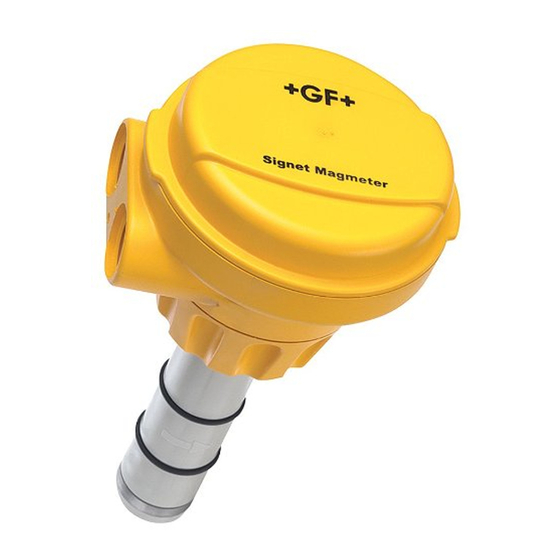
Signet 2551 Blind Magmeter
*3-2551.090*
3-2551.090
Rev L 10/12 English
Topic:
1. Quick Start Guide
2. Speci¿ cations
3. Installation: Pipe Fittings
4. Selecting a Location
5. Hardware Con¿ guration
6. General Installation and Grounding Tips
7. Wiring the Magmeter with 4 to 20 mA Loop
Description
The Signet 2551 Magmeter is an insertion-style magnetic À ow sensor. The patented sensor design is available in a variety of corrosion-
resistant materials to provide long-term reliability and minimal maintenance costs. Wetted material combinations include PP/316 SS,
PVDF/Hastelloy-C and PVDF/Titanium. The 2551 installs quickly and securely into a wide selection of À ow ¿ ttings to deliver accurate
À ow measurement in pipe sizes ranging from DN15 to DN900 (½ in. to 36 in.).
Signet 2551 Magmeters are available with a frequency output or Digital (S
Multi-Parameter Controller or 9900 Transmitter, or with a 4 to 20 mA output for a direct input to a PLC, SCADA or telemetry system.
All 2551 Magmeters feature empty pipe detection and LED-assisted diagnostics. The Signet 3-0250 USB to Digital (S
available to customize every performance feature in the 2551 to adapt it to the speci¿ c application requirements.
1. Quick Start Guide
This manual contains the general installation, wiring and calibration data for the Signet 2551-XX-11 Magmeter with Frequency or
Digital (S
3
L) data output, and for the Signet 2551-XX-12 Magmeter with 4 to 20 mA output. The basic steps are outlined on this page.
See each referenced section for detailed information.
1.
Con¿ gure the Hardware
2551-XX-11 ONLY: Position this Jumper to select
Digital (S
3
L) output or Frequency output. Sec. 5 Pg. 4.
2.
Position the PIPE SIZE jumper according to your
pipe size. Sec. 5 Pg. 4.
3.
Install the Magmeter into the pipe.
Use Signet installation ¿ ttings ONLY.
The installation ¿ tting is critical to Magmeter
performance. Sec. 3 Pg. 3.
4.
Connect POWER and OUTPUT wiring.
Frequency out: Sec. 8.1 Pg. 6.
Digital (S
3
L) out: Sec. 8.2 Pg. 6.
4 to 20 mA out: Sec. 7 Pg. 5.
GROUNDING
Without a good earth ground, the Magmeter may not
operate ef¿ ciently. Sec. 6 Pg. 5.
5.
Route the wiring out through the two cable ports.
Use appropriate hardware to secure the 2551 from
moisture intrusion. One Liquid Tight Connector is
included. Sec. 5 Pg. 4.
Page
Topic:
1
8. Wiring the Magmeter
2
with Frequency or Digital (S
3
9. Calibration and Software Con¿ guration
3
10. Calibration Data
4
11. Maintenance and Troubleshooting
5
12. Ordering Information
5
3
L) output for use with the Signet 5600 Batch Controller, 8900
1.
FREQUENCY OUT
3
SERIAL (S L) OUT
2.
Sensor Type
Pipe Size
2551-P0/T0/V0
½ in. to 2½ in.
DN15 to DN65
2551-P0/T0/V0
3 in. to 4 in.
DN80 to DN100
2551-P1/T1/V1
5 in. to 6 in.
DN125 to DN150
2551-P1/T1/V1
8 in.
DN200
2551-P2/T2/V2
10 in. to 12 in.
DN250 to DN300
3
L) Output
Connect output signals and power
to this 4-terminal block.
4
3
2
1
Jumper Position
4.
3.
English
Page
6
6
7
11
12
3
L) set-up tool is
4.
5.
Advertisement
Table of Contents

Subscribe to Our Youtube Channel
Related Manuals for Signet 2551


Summary of Contents for Signet 2551
- Page 1 This manual contains the general installation, wiring and calibration data for the Signet 2551-XX-11 Magmeter with Frequency or Digital (S L) data output, and for the Signet 2551-XX-12 Magmeter with 4 to 20 mA output. The basic steps are outlined on this page. See each referenced section for detailed information.
-
Page 2: Speci¿ Cations
Frequency output: 11.7 • Max. Pull-up 11.0 Voltage: 30 VDC 10.3 • Compatible with Signet 5600, 8900, 9900 Digital (S L) Output: • Serial ASCII, TTL level 9600 bps • Compatible with Signet 8900, 9900 Environmental Requirements • Case: • Display: Polyamide Storage Temperature: -20 to 70 °C (-4 to 158 °F) -
Page 3: Selecting A Location
Signet Flow Transmitter ENTER • The 2551 requires a full pipe and a fully developed turbulent À ow pro¿ le for accurate Flow measurement. • If the piping system harbors air pockets or bubbles, take steps to locate the sensor so the air pockets will not contact the electrodes. - Page 4 Whether using the 2551-XX-11 (with frequency or Digital (S The user must connect output cables to JP2 is for factory use only. output) or the 2551-XX-12 (with 4 to 20 mA output), the wiring this 4-terminal block. MAKE NO CONNECTIONS.
-
Page 5: General Installation And Grounding Tips
20 —S/cm.) Grounding The 2551 Magmeter is unaffected by moderate levels of electrical noise. However, in some applications it may be necessary to ground portions of the system to eliminate electrical interference. The grounding requirements will vary with each installation. - Page 6 9900 manual for complete information. 9. Calibration and Software Con¿ guration No calibration is necessary to begin using the 2551. The application and performance settings are pre-set to meet the requirements of most applications. The 2551 application and performance settings can be customized using the Signet 3-0250 USB to Digital (S L) Con¿...
- Page 7 166.66 630.81 2½ PV8S025 123.72 32.69 242.49 917.82 PV8S030 75.81 20.03 395.71 1497.76 PV8S040 41.87 11.06 716.56 2712.19 PV8S060 19.71 5.21 1521.92 5760.46 PV8S080 11.73 3.10 2558.12 9682.50 PV8S100 7.43 1.96 4037.60 15282.3 PV8S120 5.23 1.38 5734.87 21706.48 2551 Magmeter...
- Page 8 PVC FITTINGS (DIN/ISO, BS, ANSI) DN15 PVMT005 2067.76 546.30 14.51 54.91 DN20 PVMT007 1136.61 300.29 26.39 99.90 DN25 PVMT010 716.52 189.31 41.87 158.47 DN32 PVMT012 446.07 117.85 67.25 254.56 DN40 PVMT015 278.83 73.67 107.59 407.23 DN50 PVMT020 159.36 42.10 188.26 712.55 2551 Magmeter...
- Page 9 7.45 1.97 4028.83 15249.13 CS4W120 5.24 1.39 5722.73 21660.53 GALVANIZED IRON TEES ON SCH 40 PIPE IR4T010 558.50 147.56 53.71 203.31 1¼ IR4T012 334.45 88.36 89.70 339.51 1½ IR4T015 248.97 65.78 120.49 456.07 IR4T020 146.00 38.57 205.48 777.76 2551 Magmeter...
- Page 10 30.99 255.74 967.96 BR4B030 78.62 20.77 381.58 1444.28 BR4B040 45.13 11.92 664.77 2516.15 BR4B050 32.79 8.66 914.91 3462.95 BR4B060 22.73 6.01 1319.87 4995.72 BR4B080 13.14 3.47 2283.68 8643.71 BR4B100 8.34 2.20 3597.17 13615.29 BR4B120 5.87 1.55 5109.58 19339.76 2551 Magmeter...
-
Page 11: Maintenance
11. Maintenance The 2551 Magmeter requires very little maintenance. There are no user-serviceable components in the Magmeter. • If the À uid contains deposits and solids that may coat the electrodes, a regular cleaning schedule is recommended. • Do not use abrasive materials on the metal electrodes. Clean with soft cloth and mild detergent only. -
Page 12: Ordering Information
Liquid-tight connector kit, 1 set, ½ in. NPT Georg Fischer Signet LLC, 3401 Aero Jet Avenue, El Monte, CA 91731-2882 U.S.A. • Tel. (626) 571-2770 • Fax (626) 573-2057 For Worldwide Sales and Service, visit our website: www.gfsignet.com • Or call (in the U.S.): (800) 854-4090 For the most up-to-date information, please refer to our website at www.gfsignet.com...
Need help?
Do you have a question about the 2551 and is the answer not in the manual?
Questions and answers