Advertisement
Quick Links
VF-G1000
USER'S MANUAL
Rev 1.3 - January 2022
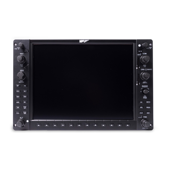
1. IN THE BOX
A) PFD/MFD Panel
B) Audio Panel
C) Power supply
D) EU power cable
E) USA power cable
F) Jack cable
G) HDMI cable
H) USB cable
I ) Set of "L"s & "U"s
supports for panel
mounting, includ-
ing M4x16 coun-
tersunk screws,
M4x8 butterfly
screws and 3mm
separators.
© 2021 Virtual Fly, SL
All trademarks and brand names are
trademarks or registered trademarks of their
respective owners. All rights reserved.
1x
B
C
1x
E
1x
F
2x
H
3x
I
C. Maria Aurèlia Capmany, 21
P.I. La Fàbrica – 08297 Castellgalí (Spain)
Phone: (+34) 983 333 301
www.virtual-fly.com
A
2x
D
1x
G
2x
8x
30x
2x
8x
10x
Advertisement

Related Manuals for Aircatglobal VirtualFly VF-G1000


Summary of Contents for Aircatglobal VirtualFly VF-G1000
- Page 1 VF-G1000 USER’S MANUAL Rev 1.3 - January 2022 1. IN THE BOX H) USB cable A) PFD/MFD Panel I ) Set of “L”s & “U”s supports for panel B) Audio Panel mounting, includ- C) Power supply ing M4x16 coun- D) EU power cable tersunk screws, E) USA power cable M4x8 butterfly...
- Page 2 2. CUT-OUT These are the measures for panel mounting. Maximum panel • OPTION 1: 4 screws from the front of the cockpit thickness = 10mm (0,393 inches). (recommended). There are two options for mounting PFD/MFD panel in the • OPTION 2: 4 supports from the back of the cockpit. cockpit: The Audio panel mounting is always from the back with 2 supports.
- Page 3 OPTION 2 - From the back 30,6 (1,20) 298 (11,73) Tolerances +0,3/-0,3 (+0,011/-0,011) You can find the BLUEPRINT measures in DXF format in our If you already have a place to mount the panels, but these DOWNLOADS G1000 section: https://www.virtual-fly.com/ are bigger than the measures, please look at section https:// setup-support www.virtual-fly.com/shop/flightpanels/g1000 of the web,...
- Page 4 3. ASSEMBLY 3.1. Select with the back switch, the panel you wish to be ATTENTION: 12vdc power supply must be disconnected for PFD and the one you wish to be MFD. Acording to the the change to take e ect. Otherwise, the device will remain picture below the PFD will be installed on the left and the in the previous state.
- Page 5 3.2. Mount the PDF/MDF panels from the front Always mount the AUDIO panel at first and then the PFD (recommended) with the countersunk screws (I). and the MFD panels. Use the supports (I) and the butterfly screws (I) for mounting audio panel.
- Page 6 You can also mount the PDF/MDF panels from the back. Use the supports (I) and the butterfly screws (I) provided. Once screwed, it is necessary to bend the supports, to get the best results VF-G1000 | User’s manual...
- Page 7 3.3. Connect the video cables to the computer where you have the G1000 simulation software installed. You have 2 options. It’s important you know that the best option is the HDMI because is a digital signal which provides more detailed graphics in the screen. HDMI option (Recommended) Use the (G) cables provided.
- Page 8 VGA option *These cables are not provided. HDMI HDMI 12vdc IN 12vdc OUT PFD - MFD 12vdc IN 12vdc OUT PFD - MFD 12vdc IN Connector Connector 12vdc OUT VF-G1000 | User’s manual...
- Page 9 3.4. Connect the USB cables to the computer where you have the G1000 simulation software installed. Use the 3 (H) cables provided. HDMI HDMI 12vdc IN 12vdc OUT PFD - MFD 12vdc IN 12vdc OUT PFD - MFD 12vdc IN Cable (H) Cable (H) 12vdc OUT...
- Page 10 3.5. Connect the power supply (C) to the PFD screen and the jack cables (F) between the PFD screen and the rest of the equipment. Jack Cable (F) HDMI HDMI 12vdc IN 12vdc OUT PFD - MFD 12vdc IN 12vdc OUT PFD - MFD 12vdc IN Jack...
- Page 11 4. CONFIGURE THE DISPLAYS IN 5. BUTTONS AND ROTARIES WINDOWS INTERFACE WITH G1000 SIMULATION SOFTWARE In Windows, open Display Settings and make sure that the two displays have the resolution set to 1024x768 pixels. It’s This chapter tells you how the push-buttons and rotaries recommendable that the MFD be placed at the right of PFD.
- Page 12 5.2. Interface with F1tech G1000 Student Pro simulation software: You have two options: Single PC configurationT wo PC configuration PC 1 PC 2 Software: Software: Software: - FSX/Prepar3D - FSX/Prepar3D - F1Tech G1000 Student (with F1Tech G1000 network module installed (with F1Tech G1000 Pro simulation software and with FSUIPC installed)
- Page 13 *VF-G1000 Hardware set up: F1Tech G1000 Student Pro set up with VF-G1000 Hardware PFD and MFD devices need to be switched to F1Tech In the “Control Panel” of F1tech select “Hardware” tab, compatibility mode. “Platform selection” and choose “VirtualFly VF 1000” option. 1.
- Page 14 5.3. Interface with default G1000 in X-Plane: First of all, we want to emphasize a tip from the developers of G1000 setup activation X-Plane: The G1000 must run on the computer that runs the • Execute VFHub. X-Plane flight model. So, the G1000 hardware must be plugged in to the computer that calculates the flight model, the same •...
- Page 15 • In X-Plane “Settings/Graphics” tab, set PFD and MFD Monitors as “Unused”. • Resize the PFD virtual G1000 window in order to fit it into the PFD display. Move the window down to the PFD display but the top window frame has to remain at the Main display.
- Page 16 5.4. Interface with MSFS VF-G1000 is completely compatible with MSFS using a custom module. This module is automatically installed by VFHub. To use the MSFS G1000 (or WorkingTitle mod) please follow these instructions: • Hold down the Alt-Gr (The ALT key to the right of the space bar) while hovering your mouse over the in-aircraft avionics, such as the PFD, MFD, or GNS gauges (your cursor will change to a + sign) and then LEFT click.
- Page 17 • To separate them into distinct windows, click the + sign. Once you have two independent windows (PFD/MFD) drag them (without changing the size) to the appropriate VFG1000 screens (they will be pretty large, just make sure to drag the portion with the icons in top right into the screen). •...
- Page 18 6. BACKLIGHTING CONTROL To turn ON/OFF the backlighting of the equipment you can control it through the equipment or from the VF-G1000-ControlPanel. From the equipment Double tap on Double tap on the the rotatory rotatory PILOT VOL push ID the backlighting PFD/MFD backlighting Rotating the rotary...
- Page 19 7. OSD Each Screen is already configurated from factory, however the user can access to the screen menus. • MENU: push “VOL SQ” (1) + move JOYSTICK “RANGE” RIGHT (2). • UP: push “VOL SQ” (1) + move JOYSTICK “RANGE” UP (2). •...
-
Page 20: Technical Data
8. TECHNICAL DATA Nominal Current: 0.1 A Voltage: 115–230 VAC, mono, 50/60 Hz. PFD/MFD PANEL & AUDIO PANEL MEASURES mm [inch] 34,6 [1,36] 300 [11,81] VF-G1000 | User’s manual...
Need help?
Do you have a question about the VirtualFly VF-G1000 and is the answer not in the manual?
Questions and answers