Table of Contents
Advertisement
Quick Links
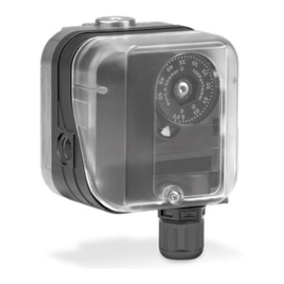
Pressure switches for gas DG..H, DG..n
Pressure switch for gas DG..I
Contents
1 Safety . . . . . . . . . . . . . . . . . . . . . . . . . . . . . . . . 1
2 Checking the usage . . . . . . . . . . . . . . . . . . . . . 2
3 Installation . . . . . . . . . . . . . . . . . . . . . . . . . . . . 2
4 Wiring . . . . . . . . . . . . . . . . . . . . . . . . . . . . . . . . 4
5 Adjustment. . . . . . . . . . . . . . . . . . . . . . . . . . . . 4
6 Tightness test. . . . . . . . . . . . . . . . . . . . . . . . . . 5
7 Maintenance. . . . . . . . . . . . . . . . . . . . . . . . . . . 5
8 Accessories . . . . . . . . . . . . . . . . . . . . . . . . . . . 5
9 Technical data . . . . . . . . . . . . . . . . . . . . . . . . . 8
10 Designed lifetime . . . . . . . . . . . . . . . . . . . . . . 8
11 Certification . . . . . . . . . . . . . . . . . . . . . . . . . . 9
12 Logistics . . . . . . . . . . . . . . . . . . . . . . . . . . . . . 9
13 Disposal . . . . . . . . . . . . . . . . . . . . . . . . . . . . . 9
oPeRAtInG InstRUCtIons
Cert. Version 08.19 · Edition 03.22 · EN · 03251237
1 sAFetY
1.1 Please read and keep in a safe place
Please read through these instructions care-
fully before installing or operating. Following the installa-
tion, pass the instructions on to the operator. This unit
must be installed and commissioned in accordance
with the regulations and standards in force. These
instructions can also be found at www.docuthek.com.
1.2 explanation of symbols
1 , 2 , 3 , a , b , c = Action
➔ = Instruction
1.3 Liability
We will not be held liable for damage resulting from
non-observance of the instructions and non-com-
pliant use.
1.4 safety instructions
Information that is relevant for safety is indicated in the
instructions as follows:
DAnGeR
Indicates potentially fatal situations.
WARnInG
Indicates possible danger to life and limb.
CAUtIon
Indicates possible material damage.
All interventions may only be carried out by qualified
gas technicians. Electrical interventions may only be
carried out by qualified electricians.
1.5 Conversion, spare parts
All technical changes are prohibited. Only use OEM
spare parts.
Advertisement
Table of Contents

Subscribe to Our Youtube Channel
Related Manuals for Krom Schroder DG H Series


Summary of Contents for Krom Schroder DG H Series
-
Page 1: Table Of Contents
Pressure switches for gas DG..H, DG..n Pressure switch for gas DG..I oPeRAtInG InstRUCtIons Cert. Version 08.19 · Edition 03.22 · EN · 03251237 1 sAFetY 1.1 Please read and keep in a safe place Please read through these instructions care- fully before installing or operating. -
Page 2: Checking The Usage
2.2 Part designations 2 CHeCKInG tHe UsAGe For monitoring increasing and decreasing gas or air pressure. Increasing negative pressurea Increasing pressure Decreasing Decreasing pressure negative pressure -6 -5 -4 -3 -2 -1 0 1 2 3 4 5 6 Upper housing section with cover negative Positive pressure pressure... - Page 3 3.1 Installation position DG..H, DG..n – positive pressure, negative pressure Installation in the vertical or horizontal position, or ➔ It is recommended that the port which is best pro- sometimes upside down, preferably with vertical dia- tected from water and dirt be left open. phragm.
-
Page 4: Wiring
DG..I – negative pressure ➔ It is recommended that the port which is best pro- tected from water and dirt be left open. negative pressure measurement at port 1 ➔ Seal port 2. M16 x 1,5: ø 4–10 mm negative pressure measurement at port 2 6 Wire as shown on the connection diagram. -
Page 5: Tightness Test
3 Connect an ohmmeter. 6 tIGHtness test Check all gas ports used for tightness. 1 Shut off the downstream gas pipeline close to the valve. 2 Open the valve and the gas supply. ➔ N = 900 mbar, max. 2 bar (13 psi, max. 29 psi) 4 Set the switching point using the hand wheel. - Page 6 8.3 external adjustment 8.5 Pressure equalization element In order to set the switching pressure from the outside, For CE certified pressure switches. the cover for external adjustment (6 mm Allen key) for To avoid the formation of condensation, the cover with DG..I can be retrofitted.
- Page 7 8.9 Fastening set with screws, U-shape brack- 8.11 standard coupler plug set 4 7 , 5 . 9 5 " ) ( 1 . 8 7 5 ( 2 7 " ) For CE certified pressure switches, Order No.: 74915388 M4 x 12 ( 0 .
-
Page 8: Technical Data
8.13 Red/green LeD for 24 V DC/AC or Max. test pressure for testing the entire system: 110–230 V AC temporarily (< 15 minutes) 2 bar. 24 V DC, I = 16 mA; 24 V AC, I = 8 mA, Order No.: Diaphragm pressure switch, silicone-free. 74921089. Housing: glass fibre reinforced PBT plastic with low 110 to 230 V AC, Order No.: 74923275. -
Page 9: Certification
11 CeRtIFICAtIon 12 LoGIstICs Declaration of conformity transport Protect the unit from external forces (blows, shocks, vibration). Transport temperature: see page 8 (9 Technical data). We, the manufacturer, hereby declare that the prod- Transport is subject to the ambient conditions de- ucts DG..H, DG..N, DG..I with product ID No. - Page 10 FoR MoRe InFoRMAtIon The Honeywell Thermal Solutions family of products includes Honeywell Combustion Safety, Eclipse, Exothermics, Hauck, Kromschröder and Maxon. To learn more about our products, visit ThermalSolutions.honeywell.com or contact your Honeywell Sales Engineer. Elster GmbH Strotheweg 1, D-49504 Lotte T +49 541 1214-0 hts.lotte@honeywell.com www.kromschroeder.com...
Need help?
Do you have a question about the DG H Series and is the answer not in the manual?
Questions and answers