Table of Contents
Advertisement
Quick Links
Advertisement
Table of Contents

Related Manuals for Grant CRF-1 Series

Summary of Contents for Grant CRF-1 Series
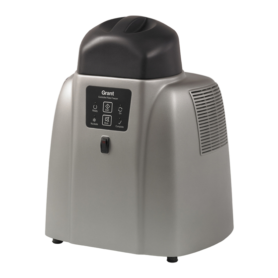
- Page 1 Controlled Rate Freezer CRF-1 Series Operating Manual...
-
Page 2: Table Of Contents
Product Description ....................... 6 1.2. Product Accessories ...................... 6 How to use this Operating Manual ................6 Safety Information ......................7 3.1. CRF-1 Series Controlled Rate Freezer ................. 7 3.2. Cryopen Nucleating Tool ....................7 Technical Specification ....................8 4.1. Operating Conditions ..................... 8 4.2. - Page 3 7.8. Starting a New Cycle ....................43 Freezing Profiles ......................44 8.1. Embryo Cryopreservation.................... 44 8.2. Oocyte Cryopreservation..................... 45 8.3. Blastocyst Cryopreservation..................45 8.4. Embryonic Stem Cell Cryopreservation ..............46 Spermatozoa Cryopreservation – Linear Cooling ............46 8.5. Oocyte – Non-Linear Cooling Cryopreservation ............47 8.6.
-
Page 4: Appendix 1
Figure 5: Software: .NET Framework Installation User Account Control ........ 12 Figure 6: Software: Install Wizard .................... 12 Figure 7: Software: Grant CRF Software Installation User Account Control ......13 Figure 8: Software: FTDI CDM Drivers Extraction ..............13 Figure 9: Software: FTDI CDM Drivers Installation ..............13 Figure 10: Software: Install Wizard Completed ............... - Page 5 Figure 46: Monitor Panel. End of Cycle ................... 42 Figure 47: Pre-programmed embryo freezing cycle ..............44 Figure 48: Pre-programmed oocyte freezing cycle ..............45 Figure 49: Pre-programmed blastocyst freezing cycle ............45 Figure 50: Pre-programmed embryonic stem cell freezing cycle ..........46 Figure 51: Pre-programmed sperm - linear freezing cycle ............
-
Page 6: Introduction
If there is a technical matter that this operating manual does not address or any other question concerning the CRF-1 product please do not hesitate to contact Grant Instruments (Cambridge) Ltd. The general details of your warranty for the CRF-1 series freezer are detailed in section 11. CRF-1 Operating Manual Page 6 of 60... -
Page 7: Safety Information
Safety Information 3.1. CRF-1 Series Controlled Rate Freezer The following symbols mean: Caution: Read these operating instructions fully before use and pay particular attention to sections containing the symbol. Read this manual before using the CRF-1 nitrogen-free controlled rate freezer. -
Page 8: Technical Specification
Technical Specification 4.1. Operating Conditions The CRF-1 is designed for operation indoors in a standard laboratory environment with temperature and humidity control, with an ambient temperature between 20°C and 30°C at altitudes up to 2000m. 4.2. Electrical Details Mains Supply: 100-240V, 50-60Hz 2.5A (max) Unit Supply: 24V DC... -
Page 9: Installation
Remove packing materials carefully, and retain them for future shipment or storage of the equipment. Inspect the unit to ensure that no damage has occurred during transit. If the unit shows any sign of damage, or any items are missing, please contact Grant Instruments immediately. -
Page 10: Pc Setup
5.4. PC Setup The CRF-1 user software can be run on any laptop or desktop computer using Windows 7 or Windows 10. However, there are several elements that must be considered before starting any data run. Ensure any laptop used has sufficient power to maintain its powered-on state during the whole run. -
Page 11: Grant Crf Software
The installation requires Windows 7 or Windows 10. In addition to loading the Grant CRF software you will also be loading the drivers for the USB to serial converter (FTDI). In the case of Windows 7 only, you will be loading Microsoft .NET 4.5 framework if this is not already installed. -
Page 12: Figure 4: Software: .Net Framework Installation
6.1.1.2. .NET framework (Windows 7 only) The installation will detect whether .Net requires to be installed. If it is already installed or if the operating system is Windows 10, then this step is skipped. Select "Install". Figure 4: Software: .NET Framework Installation You will also be prompted by the user account control. -
Page 13: Figure 7: Software: Grant Crf Software Installation User Account Control
The software will start installing. User Account Control will ask if you wish to make changes. Select "Yes". Installation will continue. Figure 7: Software: Grant CRF Software Installation User Account Control You will then be asked if you wish to extract the FTDI drivers. These are required for the USB to serial converter that you will use to make the hardware connection to the CFR. -
Page 14: Logging In
6.1.2. Logging in Start the software by either double-clicking on the shortcut icon on your desktop (Figure 11) or by selecting ‘Grant CRF Software' from the program list in the start menu on your computer. Figure 11: Desktop shortcut icon When the software is run for the first time the default User ID is Admin and the default Password is Admin1 (see Figure 12). -
Page 15: Crf-1 Connection & Synchronisation
6.1.3. CRF-1 connection & synchronisation Wait at least 15 seconds after turning the CRF-1 on before trying to connect. To establish the connection, click the Connect button at the bottom of the software (see Figure 13). The CRF- 1 and software will synchronise with each other. While this occurs, two bars show the progress. -
Page 16: Establishing Communications With The Freezer Unit
6.2. Establishing communications with the freezer unit Ensure the computer is connected to the unit using the serial communications lead or USB to Serial converter. On the Monitor panel, click on the ‘Connect’ button as shown below. The ‘Comms Status’ at the bottom of the panel will change to ‘Status: Connected’. -
Page 17: Figure 16: Software: Status Bar
Figure 16: Software: Status bar The software suite can now be used to control the freezing cycle as well as configure the freezer, edit and create new freezing cycles, as well as generate reports with graphs and data of each freezing cycle run. CRF-1 Operating Manual Page 17 of 60 33801-V4 DMN S90... -
Page 18: Running A Profile
6.3. Running a profile Profiles can be set up and run using the Monitor page. Figure 17: Software: Choosing Profile 6.3.1. Selecting the profile & details Before running a cooling profile check the following are correct: • The cooling profile •... -
Page 19: Running The Profile
The location and filename of the directory where the log files are stored should be confirmed before starting the run. Note: The default settings for the profile details can be changed using the Software Config page (see Section 6.7 for further details) 6.3.2. -
Page 20: Running A Tsv Log File Conversion
Figure 18: Software: Generating PDF Reports 6.4.1.3. Generating TSV reports Click TSV Standard Report or TSV Detailed Report to produce a TSV report. Browse to an GEF log file using the dialog box which appears then click Open. The relevant report should be saved in a suitable location using the dialog box which appears (see Figure 19). -
Page 21: Generating An Event Log Report
6.4.3. Generating an event log report The software automatically creates a log of all key events as an encrypted GEF file. This information includes every user interaction, condition and profile status. Click PDF Event Log in the Reports window on the Report page. Highlight the event log GEF file and click Open. The PDF report will appear in the viewing area. -
Page 22: Editing An Existing Profile
Figure 20: Software: Profile Editor 6.5.1. Editing an existing profile The following sections provide information about how to change cooling profiles. Note: When connected to a CRF-1 the changes made in the software are applied immediately to the cryocooler. Backups of all profiles or individual profiles should be created before making any significant changes. -
Page 23: Setting The Parameters Of A Profile
6.5.1.3. Deleting a segment Click the ID box of the segment to be deleted. The number is highlighted in light blue to show it has been selected. Click the Delete Segment button. The segment is removed and the ID numbers for the other segments are adjusted. 6.5.1.4. -
Page 24: Figure 23: Software: Profile Editor - Segment Type
Dwell – temperature is maintained at the target temperature for a defined time Step – makes a step change of the temperature, the CRF-1 will react as fast as it is able Note: Segment 1 will always be automatically set as a Step segment. The parameter values for this segment cannot be changed except the Audible Alarm. -
Page 25: Figure 24: Software: Profile Editor - Segment Duration
This value is predefined and should not need to be altered. Note: If the value displayed for a new segment is very different from the existing values please contact your distributor or Grant for support and advice. 6.5.2.8. Setting the segment hold back This value is predefined and should be set to Off. -
Page 26: Saving & Loading Profiles
become stable at the start temperature. During this phase the temperature may ‘overshoot’ but will quickly stabilise. The Ready Light can be used to indicate when a specific stage of a profile is reached but this is normally rare. The Nucleate Light is normally used to indicate when a nucleation phase occurs and when there is a need for manual intervention (i.e. -
Page 27: Creating & Restoring Backups
Figure 27: Software: Saving Profiles Note: If the user input name (Profile2 in Section 6.5.3.1) is changed when saving the profile (e.g. to Profile3) the filename will use the new name BUT the name of the profile (as it appears in the name box on the Profile Editor page) will still be Profile2. It is therefore recommended that the default profile filename is used to avoid confusion. -
Page 28: Figure 28: Software: Creating Backup
Figure 28: Software: Creating backup 6.5.4.2. Restoring a backup Click on Restore in the Profile Management window to restore a backup of all of the profiles. Select the backup to restore from the list in the Open dialog box and click Open. The Restore Profile Selection dialog box opens (see Figure 29). -
Page 29: Designing And Configuring Reports
The header fields on the top left and top right can be set to either an image or text using the Text box or the Logo box. Figure 30 shows an example where ‘Grant.jpg’ has been added to the left hand Logo box and ‘Program Series A1’ text added to the right-hand Text box. -
Page 30: Figure 30: Software: User Defined Report Header
Figure 30: Software: User Defined Report Header These user defined conditions will appear at the top of a generated report (see Figure 31) Figure 31: Software: User Defined Report CRF-1 Operating Manual Page 30 of 60 33801-V4 DMN S90... -
Page 31: Report Template Storage Location
6.6.2. Report template storage location The default storage location of the report template is defined in the Report window on the Software Config page. This location can be changed if required. 6.7. Configuring the software All parameters and defaults can be changed in the Software Config page. 6.7.1. -
Page 32: Figure 33: Software: User Defined Conditions
Figure 33: Software: User Defined Conditions To add user specific text to the file name, such as an assay name, ensure that the Include Text box in the Log window on the Software Config page is checked (see Figure 34) When the Include Text box is checked –... -
Page 33: Report Configuration Options
Figure 34: Software: User Text 6.7.2. Report configuration options The default storage location and naming format for reports is defined in the Report window on the Software Config page. The default report name is composed of three fields Date_Time_Serial Number in a similar manner to the log file naming. If any of these fields is not required then the relevant box (Include Date, Include Time, Include Serial) should be unchecked. -
Page 34: Communication Configuration Options
6.7.6. Communication configuration options The appropriate Com Port that is connected to the CRF-1 can be set using this option. Baud Rate should always be set to 9600. 6.8. Users The software is programmed with one administrator level user: User ID: Admin; Password: Admin1. -
Page 35: Editing Existing Users
6.8.2. Editing existing users Click the user that needs to be changed in the Quick Nav – Users window. Select Edit from the Select Mode window. The fields in the User Details are updated to show the selected users information. Update the required information and click Update. Be sure not to edit the Administrator's User Level. -
Page 36: Operating Procedure For The Crf-1 Freezer
Operating Procedure for the CRF-1 Freezer 7.1. Pre-operation Checks Before operating, ensure that: The freezer has been installed and switched on (Section 5) The software suite has been opened and communications established (Sections 6) It is recommended that an initial test run is completed using the maximum volume of liquid allowed at the fastest cooling rate to ensure that everything has been set up correctly. -
Page 37: Figure 37: 0.25Ml Imv Straws Positioned On Sample Plate
7.3.1.2. CRF-1 H01 – 0.25ml IMV Straws The CRF-1 H01 is designed for the controlled rate freezing of 0.25ml capacity straws, for example the CBS Paillette Cristal. Load up to 18 straws as normal and seal with a straw plug, cristaseal etc. -
Page 38: Figure 39: Sbs Microplate Positioned On Sample Plate
7.3.1.4. CRF-1 H03 – Flat Plate The CRF-1 H03 has been designed with a flat plate to accommodate non-standard vessels. Note that it is recommended that the user performs one or more test runs to ascertain that the required cooling rate can be achieved with the intended vessel and volume of liquid, see Appendix 1 for more help. -
Page 39: Starting The Freezing Cycle
7.4. Starting the Freezing Cycle When the samples have been positioned correctly, put the lid back on. A few more minutes may be required for the plate temperature to stabilise again. When it is ready to start, the Cryocooler status will show ‘Cycle Ready’ Follow the instructions below to start the freezing cycle profile. -
Page 40: Figure 41: Monitor Panel. Time To Nucleation
Figure 41: Monitor Panel. Time to Nucleation When the samples reach the nucleation plateau temperature, the time displayed changes to ‘Nucleate’. The freezer unit buzzer sounds and the yellow ‘Nucleate’ light on the freezer unit illuminates. Nucleation should be done at this time. The programs normally allow a 10 minute period for the samples to be nucleated, unless otherwise specified. -
Page 41: Figure 43: Nucleation Of Cbs Straws (Crf-1 H00)
Remove the lid of the freezer completely. Turn off the buzzer by pressing the ‘Buzzer Off’ button on the keypad. Touch the nucleating tool (if using the cryopen please refer to the operating instructions for safe use) to the first sample for approximately one second (Figure 43, Figure 44 &... -
Page 42: End Of Freezing Profile
7.6. End of Freezing Profile When the freezing profile is complete the ‘Program Time Remaining’ will show ‘Complete’ on the Monitor panel. On the freezer unit the yellow ‘Complete’ light will illuminate and the buzzer will sound. The samples can now be removed from the freezer and placed in long term storage. -
Page 43: Starting A New Cycle
7.8. Starting a New Cycle Once the freezer has returned to and stabilised at the start temperature, the Cryocooler Status will change to ‘Cycle Ready’. The ‘Start Cycle’ button will no longer be greyed out and more samples can be loaded in preparation for another freezing cycle. Remember to dry the sample plate between cycles to prevent vessels sticking during the freezing cycle. -
Page 44: Freezing Profiles
Freezing Profiles The CRF-1 series freezers are pre-loaded with specific cooling profiles. 8.1. Embryo Cryopreservation Profile name: Embryo Applicable model H00, H01, H03, H07, H08 Start temperature 20°C Cool from 20°C to -7°C at 2°C min Hold for nucleation at -7°C for 10 minutes Cool from -7°C to -30°C at 0.3°C min... -
Page 45: Oocyte Cryopreservation
8.2. Oocyte Cryopreservation Profile name: Oocyte Applicable models: H00, H01, H03, H07, H08 Start temperature 20°C Cool from 20°C to -8°C at 2°C min Hold for nucleation at -8°C for 10 minutes Cool from -8°C to -30°C at 0.3°C min Cool from -30°C to -33°C at 3°C min Cool... -
Page 46: Embryonic Stem Cell Cryopreservation
8.4. Embryonic Stem Cell Cryopreservation Profile name: Stem Cell Applicable models: H00, H01, H03, H07, H08 Start temperature 20°C Cool from 20°C to -7°C at 2°C min Hold for nucleation at -7°C for 10 minutes Cool from -7°C to -80°C at 1°C min Hold at -80°C Transfer to storage... -
Page 47: Oocyte - Non-Linear Cooling Cryopreservation
8.6. Oocyte – Non-Linear Cooling Cryopreservation Profile name: OocyteNL Applicable models: H00, H01, H03, H07, H08 Start temperature 20°C Cool from 20°C to -7°C at 2°C min Hold for nucleation at -7°C for 10 minutes Cool from -7°C to -18.1°C at 0.5°C min Cool from -18.1°C to -22.2°C at 0.4°C min Cool... -
Page 48: Cryovial Cryopreservation
These profiles are for testing and calibrating the freezer unit. Please do not edit or remove these profiles. For further information on how to test and calibrate your freezer unit contact Grant Instruments. CRF-1 Operating Manual Page 48 of 60... -
Page 49: Scientific References
Scientific References Kim SJ, Park JH, Lee JE, Kim JM, Lee, JB, Moon, SY, Roh SI, Kim CG and Yoon, HS (2004) Effects of type IV collagen and laminin on the cryopreservation of human embryonic stem cells. Stem Cells 22, 950-961. Lasalle P, Testart J and Renard JP (1985) Human embryo features that influence the success of cryopreservation with the use of 1, 2 propanediol. -
Page 50: Maintenance And Service
Servicing and calibration should only be completed by Grant Instruments Service Department or via a Grant Instruments worldwide distributor. A service contract for the CRF-1 series freezers is available. For full details of the service contract, calibration and verification please contact Grant Instruments. -
Page 51: Warranty
Agency; this reference number is WEE/GA0048TZ. For other countries please contact your equipment supplier. For General WEEE information please visit: www.b2bcompliance.org.uk Please note that because it contains a pressure vessel the CRF-1 series freezer is treated as “Special Waste”. 12.2. RoHS Directive All the products covered by this manual comply with the requirements of the EU RoHS 2 Directive (Directive 2011/65/EU). -
Page 52: Appendix 1 Troubleshooting
Check the power lead is plugged into a socket and that the socket is switched on. The protective fuse in the CRF-1 unit has blown Contact Grant Service Department. A1.3 The Software Suite will not Communicate with the Freezer Unit. -
Page 53: Appendix 2 Cryopen Nucleating Tool Operation
The samples may be damp and as they fit tightly into the plate they may have frozen onto the plate. Ensure the samples are dry before freezing (Section 7.3). Samples can be removable with careful use of tweezers. Appendix 2 Cryopen Nucleating Tool Operation Please read the instruction manual supplied with the cryopen before use. -
Page 54: Appendix 3 Comms Set-Up When Using The Usb To Serial Converter
Appendix 3 Comms set-up when using the USB to Serial converter The USB to Serial Port converter supplied with the unit has a device driver that must be installed on your computer before it can be used. Follow the instructions below. Take the mini-CD supplied with the converter and insert it into the CD/DVD drive of your PC. -
Page 55: Figure 55: Configuring The Com Port On The User Software
This should be used when setting the COM port in the Software Config panel of the User Software Suite. See Figure 55. Figure 55: Configuring the Com Port on the User Software CRF-1 Operating Manual Page 55 of 60 33801-V4 DMN S90... -
Page 56: Unpacking Instructions
Appendix 4 Unpacking instructions THE CRF-1 IS A DELICATE SCIENTIFIC INSTRUMENT AND SHOULD BE HANDLED WITH CARE AT ALL TIMES. THESE INSTRUCTIONS MUST BE FOLLOWED TO UNPACK THE UNIT. WARNING: ENSURE TRANSIT BOLT IS REMOVED BEFORE OPERATING THE UNIT, SEE TRANSIT BOLT INSTRUCTIONS BELOW. 1. -
Page 57: Appendix 5 Packing Instructions
1.Place CRF-1 Unit into a large polythene bag (Grant part no. 00402). 2. Run the packing strap (Grant part no. 29159) under the bottom foam piece and sit the unit on the foam with the cut corners of the foam facing forwards as shown. -
Page 58: Appendix 6 Transit Bolt
Appendix 6 Transit Bolt THE CRF-1 CONTROLLED RATE FREEZER IS A DELICATE SCIENTIFIC INSTRUMENT AND SHOULD BE HANDLED WITH CARE AT ALL TIMES. THESE INSTRUCTIONS MUST BE FOLLOWED TO REMOVE THE TRANSIT BOLT ATTACHED TO THE UNIT BASE PLATE. FAILURE TO REMOVE THE TRANSIT BOLT BEFORE OPERATION MAY RESULT IN UNIT DAMAGE AND MAY VOID THE PRODUCT WARRANTY 1. - Page 60 Grant Instruments (Cambridge) Ltd Representative in the European Union Shepreth Grant Instruments Europe B.V Cambridgeshire Strawinskylaan 411 SG8 6GB WTC, Tower A, 4th Floor 1077 XX AMSTERDAM THE NETHERLANDS Tel: +44 (0) 1763 260811 salesdesk@grantinstruments.com grant@eu.grantinstruments.com www.grantinstruments.com...
Need help?
Do you have a question about the CRF-1 Series and is the answer not in the manual?
Questions and answers