Biral BTD-200 User Manual
Field test unit
Hide thumbs
Also See for BTD-200:
- User manual (69 pages) ,
- Software update instructions (21 pages) ,
- User manual (23 pages)
Table of Contents
Advertisement
Quick Links
Advertisement
Table of Contents

Related Manuals for Biral BTD-200


Summary of Contents for Biral BTD-200
- Page 1 BTD-200 Field Test Unit Manual Number: 107842.00B Revision:...
-
Page 3: Table Of Contents
Batteries ..................... 2 Inappropriate Use ..................2 Environmental Conditions ................2 BOX CONTENTS ..................3 BTD-200 FIELD TEST UNIT OPERATING INSTRUCTIONS ...... 4 Pre-test Preparation ..................4 OPERATION ................... 8 Antenna/Earth Reference Connections ............8 Power-On FTU Handheld Unit ..............11 Operator Location during Test .............. -
Page 4: Primary Function
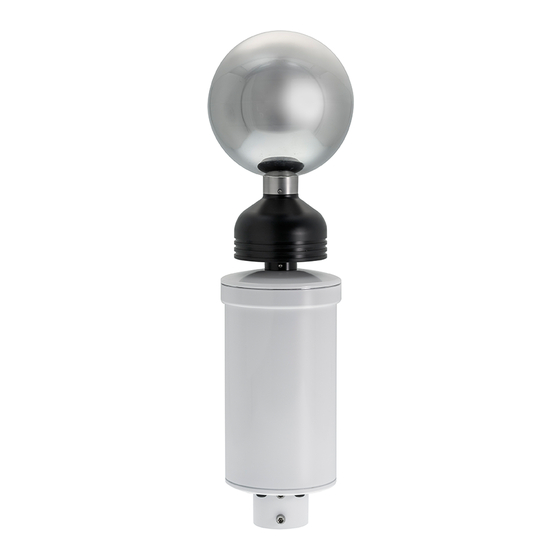
PRIMARY FUNCTION The Biral BTD-200 Field Test Unit (FTU) simulates lightning flashes, strong electric fields and charged precipitation. It is intended for checking the operation of Biral BTD- 200 thunderstorm warning systems and any connected accessories. NOTE: Not for BTD-200 calibration, validation of sensor siting requirements or confirming correct installation. -
Page 5: Box Contents
BOX CONTENTS The following equipment is supplied in the BTD-200 FTU carton. Please check the contents carefully and immediately report any missing items to your supplier. 1x FTU Handheld unit 1x PP3 9V Battery 1x Primary Antenna Clamp 1x Secondary Antenna Clamp... -
Page 6: Btd-200 Field Test Unit Operating Instructions
BTD-200 FIELD TEST UNIT OPERATING INSTRUCTIONS Pre-test Preparation 4.1.1 Test Environment NO OVERHEAD OBSTRUCTION NO PLANTS OR OBJECTS >20CM TALL WITHIN 2M NO PERSON OR VEHICLE MOVEMENT WITHIN 5M NO THUNDERSTORM ACTIVITY WITHIN 45KM (25 MILES) NO PRECIPITATION – NO RAIN, SNOW ETC.. - Page 7 4.1.2 Lightningworks software testing setup (optional software) 4.1.2.1 Set Range settings to Overhead 8Km, Vicinity 16Km, Distant 35Km (Defaults) Range Settings Site Correction Settings NOTE: Record settings if not standard/defaults, these will require resetting after FTU testing 4.1.2.2 Set Site Correction Factor (Current SCF) to ‘1’ using the following method Record ‘Current SCF’...
- Page 8 4.1.3 FTU Battery installation 4.1.4 Antenna Cleaning 4.1.4.1 Using the Microfibre Cloth, wipe and dust, dirt and debris, from the contact areas on both antennae before starting any testing. WIPE CLEAN WIPE CLEAN...
- Page 9 Self-Test Status 4.1.4.2 Ensure system self-test status is healthy via either Lightningworks or on- sensor indicator Health Status LED System Healthy – Solid Green System Fault – Blinking Green...
-
Page 10: Operation
OPERATION Antenna/Earth Reference Connections 5.1.1 Attach clip to Earth Stud at Base of BTD-200 FTU Cable Assembly Earth Stud 5.1.2 Attach Primary Antenna Clip ‘Click’... - Page 11 5.1.3 Attach Secondary Antenna Saddle...
- Page 12 5.1.4 Connect Primary and Secondary Antenna Clamps to the Cable Assembly: 5.1.5 Connect Antenna Assembly to FTU Handheld Unit ‘Click’...
-
Page 13: Power-On Ftu Handheld Unit
WARNING: Field Test Unit will not execute tests if low battery is indicated. Both touch buttons will be deactivated Operator Location during Test Move away from the BTD-200 to the maximum extent of the Cable. Do not pull the Cable tight. Remain still for the duration of the tests. -
Page 14: Conducting A Test
Conducting a Test WARNING: Ensure pre-test criteria (section 4.1) conditions are met before commencing testing 5.4.1 Selecting a Test Touch ‘Select’ Button to cycle through test options to desired test sequence. Test Selection Indicators Select Button 5.4.1.1 Test Options Test Name Description Range and Event Time Simulation of strong atmospheric... - Page 15 5.4.2 Activating a Test Touch ‘Activate’ button to start selected test Touch Activate Button Selected test indicator will flash for 15 seconds to allow user to vacate BTD area Test LED will then Flash rapidly during test process For ‘Full Sequence’ testing the indicator will remain solid.
-
Page 16: Test Results/System Behaviour
Test Results/System Behaviour 5.5.1 For systems using Lightningworks. Map Visualisation Alert Warning Activity Log Flash Count Fields 5.5.1.1 Map Visualisation & Flash Count Fields Zone Map Highlight Flash count in last 60 minutes Zone 1 Highlights yellow during 'Distant' test 2 flashes in 16-35Km field Zone 2 Highlights yellow during 'Vicinity' test... - Page 17 5.5.1.3 Activity Log entry format [Alarm type][Thunderstorm activity type : Distance][Event Date][Event Time] 5.5.1.4 ‘Full Sequence’ Activity Log example Warning – Distant: 19 Km 24/05/2021 15:19:43 Warning – Distant: 19 Km 24/05/2021 15:19:46 Warning – Vicinity: 10 Km 24/05/2021 15:19:49 Warning –...
-
Page 18: Ending Btd-200 Test Procedure
Ending BTD-200 Test Procedure... - Page 21 Disconnect...
-
Page 22: Storage
House, North Point Business Park, New Mallow Road, Cork, T23 AT2P, Ireland Maintenance and Calibration The BTD-200 FTU is used to check the operation of the BTD-200 sensor, it is not a calibration device. The BTD-200 FTU does not require any periodic maintenance or calibration. -
Page 23: One Year Warranty
The information contained in this manual (including all illustrations, drawings, schematics and parts lists) is proprietary to BIRAL. It is provided for the sole purpose of aiding the buyer or user in operating and maintaining the equipment. This information is not to be used for the manufacture or sale of similar items without written permission.
Need help?
Do you have a question about the BTD-200 and is the answer not in the manual?
Questions and answers