Advertisement
Quick Links
INSTRUCTION MANUAL
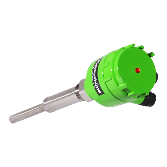
Vibrating Level Switch
TYPE: MVL-110 / MVL-120/ MVL-130
Safety Precautions
1. Outline
2. Specifications
3.Profile
4. Mounting
5. Connection
6. Commissioning
7. Troubleshooting
※The operator should read this Instruction Manual carefully and
handle the device correctly.
1-8-18 Norimatsu-Higashi,Yahatanishi-ku,Kitakyushu 807-0837 Japan
Phone No.(8193)691-3731 Fax No.(8193)691-3735
http://www.matsushima-m-tech.com
E-mail sales@matsushima-m-tech.com
FOR
Contents
・・・・・・・・1
・・・・・・・・1
・・・・・・・・2
・・・・・・・・3
・・・・・・・・4
・・・・・・・・5
・・・・・・・・7
TMVL-001E
Rev2:Apr.26,2019
Advertisement

Related Manuals for Matsushima MVL-110

Summary of Contents for Matsushima MVL-110
- Page 1 TMVL-001E Rev2:Apr.26,2019 INSTRUCTION MANUAL Vibrating Level Switch TYPE: MVL-110 / MVL-120/ MVL-130 Contents Safety Precautions 1. Outline ・・・・・・・・1 2. Specifications ・・・・・・・・1 3.Profile ・・・・・・・・2 4. Mounting ・・・・・・・・3 5. Connection ・・・・・・・・4 6. Commissioning ・・・・・・・・5 7. Troubleshooting ...
-
Page 2: Safety Precautions
Cause for any peripheral equipment or device. d. Accident beyond control and force majeure (fire, earthquake, flood, riots, etc.). Lack of instructions to MATSUSHIMA for information or safety requirements that can be predicted only by customers’ side. This warranty conditions do not limit customers’ legal right. -
Page 3: Specifications
1.Outline Vibrating level switch can detect a storage level of particulate materials from very lightweight powders to grains. Vibrating probe will oscillate in a fixed frequency (resonant frequency) by piezo element, if coating with powders of storage materials, vibrating amplitude will be significantly decreased. This decreased amplitude will be detected by the part of electronic circuit, and a contact signal is output as a level signal. 2.Specifications Table 1. Standard specifications Type MVL-110 MVL-120 MVL-130 Product type Standard Cable suspended Extension pipe Power AC/DC22 to 264V 50/60Hz Power consumption 4.7W(AC),1.8W(DC) Housing :ADC12(Aluminum diecasting) Boss :SUS316L Material Probe :SUS316L ... - Page 4 (Hexagon nut 41) (Hexagon nut 41) (Hexagon nut 41) R1 Screw R1 Screw R1 Screw Note 1 Extension pipe Vibrating probe MVL-110 MVL-130 Note 1 Use the screws of G(JIS B 0202) and Rp(JIS B2003) for facility Vibrating probe to mount switches. And use nozzle pipes of over 32A for mounting. MVL-120 ...
- Page 5 4.Mounting 4-1.Mounting devices If mounting a device, screw Boss (Hexagon part) using a spanner etc. after sealing a screw part. Note:Please do not screw by turning a case part. 4-2.Protection of vibrating probe (cable) Mount the vibrating probe (cable) not to be hit by charging powders. Prevent impact by mounting a protection plate to avoid damage and disconnection if the vibrating probe is hit by the charging material. Keep over 200mm of a distance between the vibrating probe and the protection plate. Fig. 2 protection of probe Important:The cable suspended type has power voltage in cable to activate the vibrating probe . Protect the vibrating probe not to directly contact with powders, because any malfunction of switch, disconnection of cables, wrong detection, electric leak and shock may occur. 4-3.Position of vibrating probe Mount the vibrating probe projecting 20mm inside the silo. ≧20mm Fig. 3 Position of Vibrating probe 4-4. At horizontal mounting Mount the switch inclined 20°deg. It can reduce the load on the vibrating probe when removing. Fig. 4 Horizontal mounting ...
- Page 6 4-5. Mounting on facility with vibration If mounting near from a vibrating source, it may cause a false detection and damages. Mount on the place far from a vibration source. Fig. 5 Mounting on facility with vibration 4-6.Waterproof measure Mount the switch to prevent water from the housing as shown in Fig. 6. The housing can be turned approx. 310 degrees. Figure of preventing Figure of downward waterdrop by bending the a cable from top lead outlet Fig. 6 Example of waterproof measure 5.Connection The terminal arrangement is shown in Fig. 7. Power supply Contact output AC/DC22-264V AC250V,5A/ 50/60Hz DC30V,5A Fig. 7 Connection 2 Important: Size of terminal screw is M3.5, recommended cable size is1.25mm . The tightening torque is 0.8 to 1.2N・m. Contact operation is shown in 6. Commissioning Fig. 9 . Note:Terminal screw cannot be removed due to screw-up terminal base.
- Page 7 6.Commissioning The below figure is a display panel. c a b Fig. 8 Display panel 6-1.Each name and function a DETECT ・ Operation LED Red light at detecting, green light at undetected ADJ volume【Factory setting:Scale 3】 b ADJ ・・・ Volume to change a vibrating level Decreasing a vibrating level if turning to Min direction to detect small bulk density of powders. (High sensitivity Min Max Low sensitivity) ・・・ Detection mode select switch c MODE 【Factory setting:H】 Switch to select for Upper limit H /for Lower limit L 6-2. Setting ADJ volume Detecting sensitivity is set 3 at ex-factory. If detecting small bulk density powders or adhering powders, readjustment may be ...
- Page 8 6-3. Setting Detection mode switch The contact output for upper and lower limit can be set by the mode switch. Contact and LED is shown as the below Detection mode chart. MODE switch Detecting Contact status LED status status H. Mode (For upper limit) L. Mode (For lower limit) At Power OFF All status Light off( clear Fig. 9 Detection mode chart ...
-
Page 9: Troubleshooting
7.Troubleshooting If the switch cannot be recovered by the below treatment, please contact us. Table 2. Troubleshooting Problem Presumable cause Treatment Reference No lighting on Power is not supplied. Supply powder. operation LED Power out of specifications Supply the specified power. P1 is supplied. See paragraph 2 (Undetected status) Bulk density of powder is Set ADJ volume to high sensitivity. P5 H. Mode: too The bulk density lower than 0.02g/cm See paragraph No red lighting on small. cannot be detected. 6-2 operation LED Vibrating probe is not Relocate the level switch in a position L. Mode: buried in powder. ...
Need help?
Do you have a question about the MVL-110 and is the answer not in the manual?
Questions and answers