Aventics Marex ECS Assembly Instructions Manual
Control head type 500-ecs
Hide thumbs
Also See for Marex ECS:
- Assembly instructions manual (56 pages) ,
- Assembly instructions manual (60 pages)
Table of Contents
Advertisement
Advertisement
Table of Contents

Subscribe to Our Youtube Channel
Related Manuals for Aventics Marex ECS


Summary of Contents for Aventics Marex ECS
- Page 1 Assembly instructions Control Head Type 500-ECS Marex ECS R417002909/06.2016...
-
Page 3: Table Of Contents
AVENTICS | ECS Control Head | R417002909–BDL–001–AA Table of Contents Table of Contents About this documentation ..........3 Validity of the documentation..........3 Required and additional documentations......4 Presentation of information ........... 4 1.3.1 Safety messages ..............4 1.3.2 Symbols ..................5 1.3.3... - Page 4 Installation conditions............31 7.1.1 Mounting orientation ............32 Connecting the control head ..........32 7.2.1 Connecting the control head to the Marex ECS Control Unit .................... 34 Commissioning ............36 Carrying out the auto-configuration ........36 Connecting to the MarexLink network ......39 Maintenance and repair ..........41 Cleaning..................41...
-
Page 5: About This Documentation
Customer version R417002871 R417002870 Customer version The Control Head Type 500-ECS is part of the Marex ECS ship control system. Unless otherwise stated in this documentation, the designation "control head" applies for all product versions single and twin. The illustrations in this document are examples only and can differ from the appearance of the actual product. -
Page 6: Required And Additional Documentations
AVENTICS | ECS Control Head | R417002909–BDL–001–AA About this documentation Required and additional documentations Before powering up the product, make sure to read and understand the necessary documents Observe the instructions for the other system components. Observe the boat’s operating instructions. -
Page 7: Symbols
AVENTICS | ECS Control Head | R417002909–BDL–001–AA About this documentation Consequences: Describes the consequences of non- observance Prevention: Describes how to avert the danger Table 3: Hazard classes according to ANSI Z535.6-2006 Warningsign, signal word Meaning Indicates a hazardous situation... -
Page 8: Abbreviations
AVENTICS | ECS Control Head | R417002909–BDL–001–AA About this documentation Table 5: Designations Designation Meaning Marex ECS Marex Easy Control System (electronic ship remote control system) MarexLink Wireless network tool to modify the settings of Marex ECS using mobile devices. -
Page 9: Safety Instructions
The control head may only be used with Marex ECS under the conditions described in these assembly instructions. The control heads described in this document cannot be... -
Page 10: Improper Use
Marex ECS Control Head with further components which are not suitable for that purpose, exposing the Marex ECS Control Head to ambient conditions which are not admissible (see chapter 13, Technical data). AVENTICS GmbH declines any responsibility for damage resulting from unintended use. -
Page 11: General Safety Instructions
You must not modify or convert the control head. Persons who install, operate, dismantle or maintain AVENTICS products must not be under the influence of alcohol, other drugs or medications which affect the responsiveness. -
Page 12: Product- And Technology-Related Safety Messages
Installation and maintenance work is subject to the country- specific safety regulations and standards of the application. As an operator of a ship which shall be equipped with a Marex ECS Control Head and further components of a ship remote control... -
Page 13: General Notes Regarding Property Damages And Product Damages
AVENTICS | ECS Control Head | R417002909–BDL–001–AA General notes regarding property damages and product damages General notes regarding property damages and product damages Cleaning Cover all openings with suitable protective caps to prevent that cleaning agent penetrates into the system. -
Page 14: Scope Of Delivery
AVENTICS | ECS Control Head | R417002909–BDL–001–AA Scope of delivery Scope of delivery The standard product delivery includes: Table 7: Standard product delivery Control Head Type 500-ECS, in one of the following product versions: R417002881, chrome-plated, single R417002880, chrome-plated, twin... - Page 15 AVENTICS | ECS Control Head | R417002909–BDL–001–AA Scope of delivery For the assembly: Drilling template Nuts M6 Washers 6.4...
-
Page 16: About This Product
The component includes a wireless LAN-module which permits a wireless information exchange with other devices. The control head is a component of Marex ECS. Depending on the software some of the functions which are described in these assembly instructions may not be supported. -
Page 17: Characteristics And Features
AVENTICS | ECS Control Head | R417002909–BDL–001–AA About this product With the single control head version, the levers form one handle which - when moved- transmits only one signal to control throttle and gearbox. The twin control head version provides two levers each of which is used to actuate independently of the other the throttle and transmission direction of one propulsion side, port or starboard. -
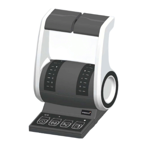
Page 18: Control Head Type 500-Ecs - Product Views
AVENTICS | ECS Control Head | R417002909–BDL–001–AA About this product 5.2.2 Control Head Type 500-ECS - Product views Fig. 1: Overview Control Head Type 500-ECS-single 1 Lever 2 Indicator 3 Scale 4 Keypad... - Page 19 AVENTICS | ECS Control Head | R417002909–BDL–001–AA About this product Port STBD Fig. 2: Overview Control Head Type500-ECS-twin 1 Levers 2 Indicator 3 Scale 4 Keypad...
-
Page 20: Ports And Connections
AVENTICS | ECS Control Head | R417002909–BDL–001–AA About this product 5.2.3 Ports and connections The following figure shows the bottom of the control head: Fig. 3: Control head, bottom view 5 Ventilaton 8 Nut and washer 6 STATION socket 9 Sealing 7 Mounting bolt 5.2.4 Levers... - Page 21 Marex ECS, it is possible to set other RPM curves which will be available temporarily or permanently. The transmission direction remains unchanged. Notice Your Marex ECS may include a special or extra function. In that case, the throttle and gearbox settings may differ from the above description.
- Page 22 AVENTICS | ECS Control Head | R417002909–BDL–001–AA About this product Lever positions NEUTRAL positon, gearbox disengaged FORWARD SLOW position, gearbox engaged to forward FORWARD position, maximum RPM REVERSE SLOW position, gearbox engaged to reverse REVERSE position, maximum RPM Fig. 4:...
-
Page 23: Keys And Functions
AVENTICS | ECS Control Head | R417002909–BDL–001–AA About this product 5.2.5 Keys and functions In the following section you will find figures depicting the keypads of Control Head Type 500-ECS, single and twin. Keys and LEDs are shown and explained. - Page 24 AVENTICS | ECS Control Head | R417002909–BDL–001–AA About this product Operating elements on Control Head Type 500-ECS: Fig. 5: Keypad Control Head Type 500-ECS single Fig. 6: Keypad Control Head Type 500-ECS-twin 1 COMMAND key with COMMAND LED(s) 2 ALARM key with ALARM LED(s)
- Page 25 AVENTICS | ECS Control Head | R417002909–BDL–001–AA About this product Table 9: Keys and functions of Control Head Type 500-ECS Element Designation Function COMMAND key with 1. Request command COMMAND LED(s) 2. Take the command over 3. Warm engine up (twin): Controlling the engines without engaging the clutch.
-
Page 26: Leds And States Of Operation
AVENTICS | ECS Control Head | R417002909–BDL–001–AA About this product 5.2.6 LEDs and states of operation The control head provides LEDs in different colors for a comprehensive overview on the control’s function.Three states of operation must be distinguished: 1. LED is permanently lit. -
Page 27: Wireless Lan-Function
Never change Marex ECS settings while the ship is moving. The control head has an integrated wireless LAN-interface which allows you to connect to the MarexLink webserver and set up your Marex ECS comfortably using your smartphone or tablet computer. -
Page 28: Classification
MarexLink webserver, you can view or change the settings of your Marex ECS ship control. Notice It depends on the version and configuration of your Marex ECS which settings are available in MarexLink. Classification The Control Head Type 500-ECS has been designed and manufactured in compliance with the generally accepted rules of technology. -
Page 29: Product Identification
AVENTICS | ECS Control Head | R417002909–BDL–001–AA About this product Product identification Fig. 7: Type plate Control Head Type 500-ECS, example 1 Material number 2 QR-Code 3 Serial number 4 Date of production 5 Software-Version... -
Page 30: Transport And Storage
AVENTICS | ECS Control Head | R417002909–BDL–001–AA Transport and storage Transport and storage Product transport NOTICE Damage due to improper transport Improper transport can cause substantial material damage. Be careful when unloading the packages on delivery and in case of in-plant transport. Observe the symbols and instructions on the package. -
Page 31: Product Storage
AVENTICS | ECS Control Head | R417002909–BDL–001–AA Transport and storage Product storage Do not destroy the packaging and only remove it shortly before installation. Adhere to the following conditions for storage: Store the control head in its original packaging. Do not store packages outside. -
Page 32: Assembly
The Marex ECS Control Head may only be installed by AVENTICS or qualified personnel as specified in chapter 2.4. Install or uninstall the Marex ECS Control Head only if the component and the system are powered off. Prepare mounting work carefully. -
Page 33: Installation Conditions
AVENTICS | ECS Control Head | R417002909–BDL–001–AA Assembly Fig. 8: Drilling template for installation (mm) Installation conditions The following installation conditions must be observed: The mounting bolts are suitable for a panel thickness between 2 to 20 mm. The mounting depth for the electric plugs and connections below the console or panel is 140 mm approximately. -
Page 34: Mounting Orientation
AVENTICS | ECS Control Head | R417002909–BDL–001–AA Assembly Use the nuts and washers supplied to mount the Control Head Type 500-ECS and fix the nuts with a maximum torque of 2 Nm. 7.1.1 Mounting orientation Always install the control head in the following sense: In cruising direction With the levers pointing upwards. - Page 35 AVENTICS | ECS Control Head | R417002909–BDL–001–AA Assembly The connectors are described in the following table: Table 12: Electrical connections of the control head Connection Socket Type Color Function required 6 STATION grey Connection to the STATION cable of 5-pin male...
-
Page 36: Connecting The Control Head To The Marex Ecs Control Unit
– digital data is transmitted by means of a CAN bus protocol – the component is supplied with power. If Marex ECS includes more than one control head, only the first Control Head Type 500-ECS is connected directly to the Marex ECS Control Unit. - Page 37 Assembly Fig. 10: Control head with terminating resistor Maximum length Up to 4 control heads can be included in Marex ECS. The STATION cable maximum length of the STATION cable is 30m with 12V- systems and 60m with 24 V-systems.
-
Page 38: Commissioning
AVENTICS | ECS Control Head | R417002909–BDL–001–AA Commissioning Commissioning The Control Head Type 500-ECS may only be used with the Marex ECS remote control system. Marex ECS must be auto- configured and tested before starting the operation. Carrying out the auto-configuration Auto-config Marex ECS features automatic configuration (auto-config). - Page 39 2. Install the Control Head Type 500-ECS and establish the electrical connections as described on page 30, Assembly. 3. Disconnect the auto-config plug from the Marex ECS Wiring Harness as shown in fig. 12. Fig. 12: Disconnect the auto-config plug 4.
- Page 40 AVENTICS | ECS Control Head | R417002909–BDL–001–AA Commissioning 5. Reattach the Autoconfig-connector to the corresponding jack on the wiring harness (fig. 13). Make sure the connector fits securely. Fig. 13: Reattach the autoconfig-connector The configuration is complete.The device status LEDs are indicating the components‘...
-
Page 41: Connecting To The Marexlink Network
AVENTICS | ECS Control Head | R417002909–BDL–001–AA Commissioning Connecting to the MarexLink network If you wish to view or modify the settings of your Marex ECS, you can easily connect to the MarexLink network by using your mobile device such as a smartphone or tablet computer. - Page 42 Alternatively, scan the following QR code: Your webbrowser must be HTML5-compatible to access MarexLink. For further information how to log on MarexLink and change the settings of your Marex ECS, use the help buttons provided within MarexLink.
-
Page 43: Maintenance And Repair
AVENTICS | ECS Control Head | R417002909–BDL–001–AA Maintenance and repair Maintenance and repair Cleaning NOTICE Product damage due to inappropriate cleaning Cleaning agents containing solvents may damage the product's surface and cause premature aging. Do only use solvent-free, non-abrasive cleaning agents Never use pressure washers or steam cleaners to clean the Control Head Type 500-ECS. -
Page 44: Disassembly And Replacement
AVENTICS | ECS Control Head | R417002909–BDL–001–AA Disassembly and replacement 10 Disassembly and replacement CAUTION Injury hazard and material damage due to unmaneuverable ship If you dismantle or replace the Control Head Type 500-ECS while the ship is moving, the ability to steer may be lost. -
Page 45: Disposal
AVENTICS | ECS Control Head | R417002909–BDL–001–AA Disposal 11 Disposal NOTICE Environmental damage due to improper disposal Electronic components require special waste treatment and must only be disposed of by approved specialist companies. Dispose of electronic scrap in an environmentally sound way. -
Page 46: Error Search And Troubleshooting
Only then acknowledge the alarm and eliminate the cause of the fault If the active control head fails, Marex ECS automatically reduces the engine rpm to idle and disengages the clutch. In case of malfunctions, check the LEDs on the control... - Page 47 AVENTICS | ECS Control Head | R417002909–BDL–001–AA Error search and troubleshooting Table 13: LED indications on the control head LED-signal Meaning What to do This control head is defective. Replace the control head and repeat the auto-configuration (see also chapters 8.1 and 10).
-
Page 48: Technical Data
125 x 154 x 123mm Weight 1kg approximately Power supply 12VDC (-25%/+30%) 24VDC (-25%/+ 30 %) (internal system power supply via Marex ECS control unit) Admissible ambient 248 to 350 K (-25C to 77°C) temperature Storage temperature 233 to 358 K (-40C to 85C) -
Page 49: Accessories
14 Accessories Part Material No. Cables POWER cable, 5m R419801567 POWER cable, 10m (not suitable for Marex ECS Actuators 12VDC) R419801316 POWER cable, dual battery connection, 5m R419801568 POWER cable, dual battery connection, 10m R419801522 (not suitable for Marex ECS Actuators 12VDC) - Page 50 AVENTICS | ECS Control Head | R417002909–BDL–001–AA Accessories Part Material No. Control head Control head type 500-ECS, single, chrome-plated R417002881 Control head type 500-ECS, twin, chrome-plated R417002880 Control head type 500-ECS, single, black R417002810 Control head type 500-ECS, twin, black...
-
Page 51: Appendix
AVENTICS | ECS Control Head | R417002909–BDL–001–AA Appendix 15 Appendix 15.1 Installation drawings 15.1.1 Control Head Type500-ECS-single Fig. 14: Dimension drawing Control Head Type 500-ECS, single... -
Page 52: Control Head Type500-Ecs-Twin
AVENTICS | ECS Control Head | R417002909–BDL–001–AA Appendix 15.1.2 Control Head Type500-ECS-twin Fig. 15: Dimension drawing Control Head Type 500-ECS, twin... -
Page 53: Alphabetical Index
AVENTICS | ECS Control Head | R417002909–BDL–001–AA Alphabetical Index 16 Alphabetical Index components 36 Abbreviations 6 Connect to Marex ECS Additional control unit 34 documentation 4 Connections 18 ALARM control cable 47 Description 14 Assembly 30 Device status LED, Installation... - Page 54 AVENTICS | ECS Control Head | R417002909–BDL–001–AA Alphabetical Index head 42 ECS-twin 22 Disposal 11 Keys and functions 23 Dispose of control head 43 Documentation LED states 24 Abbreviations 6 Length Designations 5 STATION bus 35 Required and Lever positions 18, 20...
- Page 55 AVENTICS | ECS Control Head | R417002909–BDL–001–AA Alphabetical Index Power supply 46 Power supply 46 Product description Protection class 46 Control Head Type 500- Temperature 46 ECS-single 15 Temperature, ambient 46 Product identification 27 Terminating Protection class 46 resistance 35...
- Page 56 German language. R417002909–BDL–001–AA Subject to modifications. © All rights reserved by AVENTICS GmbH, even and especially in cases of proprietary rights applications. It may not be reproduced or given to third parties without its consent.
Need help?
Do you have a question about the Marex ECS and is the answer not in the manual?
Questions and answers