Advertisement
Available languages
Available languages
Quick Links
QK-RADAROMNI
User Manual
Manuale d'uso
V03
w w w . q u i k o i t a l y . c o m
ATTENZIONE!! Prima di effettuare l'installazione, leggere attentamente questo
manuale che è parte integrante di questa confezione.
WARNING!! Before installing, thoroughly read this manual that is an integral
part of the pack
Il marchio CE è conforme alla direttiva europea CEE
89/336 + 93/68 D.L.04/12/1992 n.476
The CE mark conforms to European directive
EEC 89/336 + 92/31 + 93/68 D.L. 04/12/1992 N. 476.
Advertisement

Related Manuals for quiko QK-RADAROMNI

Summary of Contents for quiko QK-RADAROMNI
- Page 1 QK-RADAROMNI User Manual Manuale d’uso w w w . q u i k o i t a l y . c o m ATTENZIONE!! Prima di effettuare l'installazione, leggere attentamente questo manuale che è parte integrante di questa confezione. WARNING!! Before installing, thoroughly read this manual that is an integral part of the pack Il marchio CE è...
-
Page 2: Technical Feature
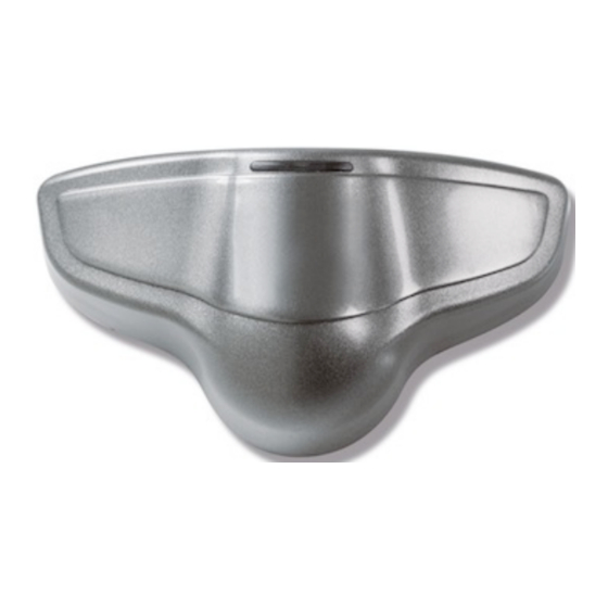
RADAR RADAR system intended particularly for sliding door applications is used to activate when the door is approached. General technical information related to the product is provided below: TECHNICAL FEATURE RADAR Dimensions Height = 78mm, Depth = 49mm, Width = 140mm Operating voltage 12-24V AC-DC ( + BROWN / - GREEN ) Minİmum current consumption 40 mA... - Page 3 Figure 3. Aligning the reception angle Figure 4. Setting operating adjustments Figure 5. Placing the upper lid...
- Page 4 Figure 6. Removing the upper lid Figure 7. Removing the bottom lid...
- Page 5 DO NOT TOUCH THE COMPONENT ON THE ELECTRONICS CARD LABELED AS “MODÜL” IN FIGURE 8 Terminal connections and technical alignment In order to adjust the controls on the electronics card, remove the upper plastic lid as illustrated in Figure 7. The components and their functions are described below in detail. VERSION 2 POT 1 A B C D...
- Page 6 POT 1, POT 2 AND POT 3 ADJUSTMENT RADAR card is equipped with 3 potentiometers, to adjust its operation scheme. Functions of these potentiometers are as outlined below: FUNCTION POT 1 With this potentiometer you can set the maximum speed of the motion you want to detect.
-
Page 7: Caratteristiche Tecniche
RADAR Sistema radar destinato in particolare per le applicazioni della porta automatica. Informazioni tecniche relative al prodotto è la seguente: CARATTERISTICHE TECNICHE RADAR Dimensioni Height = 78mm, Depth = 49mm, Width = 140mm Tensione 12-24V AC-DC = Filo (Marrone +) (Verde -) Consumo di corrente 40 mA Massima distanza di funzionamento... - Page 8 Figura 3. Allineamento angolo di ricezione Figura 4. Regolazione parametri Figura 5. Posizionamento del coperchio superiore...
- Page 9 Figura 6. Rimozione del coperchio superiore Figura 7. Rimozione del coperchio inferiore...
- Page 10 NON TOCCARE LE COMPONENTI SULLA CENTRALINA CON L'ETICHETTA "MODUL" IN FIGURA 8 Connessioni morsetti e allineamento tecnico Al fine di regolare i controlli sulla scheda elettronica, rimuovere il coperchio di plastica superiore come illustrato nella figura 7 I componenti e le loro funzioni sono descritte di seguito. VERSIONE 2 POT 1 A B C D...
- Page 11 POTENZIOMETRI POT 1, POT2, POT3 La scheda RADAR ha 3 REGOLAZIONI è dotato di 3 potenziometri, per adeguare il funzionamento. Le funzioni di questi potenziometri sono come indicato di seguito: FUNZIONE POT 1 Con questo potenziometro è possibile impostare la velocità di reazione. Rotazione POT1 in senso orario (+), massima reattività...
- Page 12 QUIKO ITALY Via Seccalegno, 19 36040 Sossano (VI) - Italy Tel. +39 0444 785513 Fax +39 0444 782371 info@quiko.biz www.quikoitaly.com...
Need help?
Do you have a question about the QK-RADAROMNI and is the answer not in the manual?
Questions and answers