Table of Contents
Advertisement
Quick Links
Detectors
Datasheet and Mounting Instruction
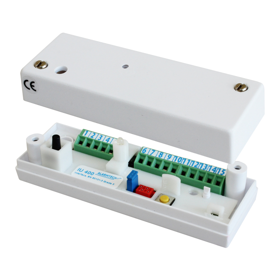
DESCRIPTION
IU 400 is an interface/analyzer for glass break detector GD 475.
It has three relays one for Intrusion, one for Fault and one for Tamper.
Max 15 units of GD 475 detectors can be connected to one IU 400 unit.
IU 400 together with GD 475 is certified according to EN 50131-1 and
EN 50131-2-7-2:2013 Grade 3, Class II.
FUNCTION
The IU 400 measures the current in a balanced alarm loop without end
of line resistance, simplifying the installation. No need to keep track of
the end of the loop. The detectors make up a balance under the control
of the IU 400 processor. An end of line resistor of 2.2kohm is only
required if the number of detectors is 3 or less. Changing the current in
the loop of +/- 0.8 mA for at least 200 ms. opens the IU 400 alarm relay
for 2-3 seconds in (AUT mode) or stays open (Latch mode) until reset
depending on how it is programmed.
The loop in IU 400 operates in the current range of 3 mA to 30 mA
corresponding to about 260 ohms to about 2600 ohms. Outside this area
the LED will flash, and alarm- and fault relays are open and the device
cannot be reset or programmed.
Reset can be done in three ways:
With the pushbutton on the device
Power supply interruption remote controlled by the control panel
Change from DAY to NIGHT connection on terminal no 5 or no. 15
DAY and NIGHT control of the detectors is done by changing the voltage
on the loop and determined by terminal 5 or 15. At DAY, the loop has 8V
and at NIGHT 6V regardless of supply voltage to IU 400 (8-30V DC).
IU 400 has two tamper switches, one for opening the cover and one for
breaking the IU 400 from the attachment.
To ensure the detector function, it monitors the voltage on the loop and
signals FAULT if the voltage exceeds or falls below the programmed
voltage.
CONNECTING THE DETECTORS
The detector GD 475 is polarity independent with a 2 core cable.
Picture below
shows how the detectors are connected to the balanced
loop. At 3 or less detectors, a 2.2 ohm resistor must be connected, with
more detectors it is not necessary.
© 2018 Alarmtech –
www.alarmtech.se
SCREW TERMINAL DESCRIPTION
1.
0 VDC
2.
10-30 VDC
3.
(-) loop
4.
(+) loop
5.
DAY/NIGHT/Reset. DAY=0V or open
6.
Intrusion relay NC
7.
Intrusion relay NC
8.
Spare
9.
Fault relay NC
10. Fault relay NC
11. Spare
12. Tamper relay NC
13. Tamper relay NC
14. Spare
15. DAY/NIGHT/Reset. DAY=V
PROGRAMMING LOOP CURRENT
Programming quiescent loop current for IU 400 is done in two steps
after connecting power and the number of detectors needed.
1.
First set the quiscent current
2.
Second set the relay mode
The IU 400 has only one jumper for programming the normal loop
current in quiescent state and the Relay mode. The quiescent current
depends on how many GD 475 there are on the loop and the end of line
resistor used. Recommended is 2,2 kohm (only necessary at 3 or less
detectors).
Changing the Jumper S1 from Open-Close-Open is telling the processor
to sense and remember the current draw. After that you can program IU
400 relays to either Momentary mode with jumper inserted or latching
mode with jumper removed. At power down the unit remembers the
recent settings and no reprogramming is needed of loop current at
power up.
S1
Open
Programming quiescent current on the loop by
Closed
changing S1 from Open to Closed to Open in a short
Open
while.
S1
Open
S1 open is LATCH mode. The relays stay open at alarm
and LED is lit until manual or remote reset.
S1
Closed
If S1 remains closed, the alarm relay will open for 2-3
seconds and then close (AUTO mode). However, LED is
lit until manual or remote reset.
Notice: The small red Micro-match contact is for production
programming and reading the built-in log using Alarmtech IU-Link
software.
INSTALLATION
1.
The IU 400 is placed within the protected area where the detectors
are mounted so that the authorized person will go there and reset
the device while inspecting the area.
2.
Connect all detectors to the loop and terminate it with a resistance
of 2.2 kohm (at 3 or less GD 475).
3.
Connect as shown in the figure.
4.
After connecting power to IU 400, wait 30 seconds, then change
the jumper S1 briefly to Open-> Closed-> Open.
5.
Select if the alarm relay is to be reset automatically (S1 = Closed) or
remain open at alarm (S1 = Open).
6.
Trigger the alarm of each detector individually to ensure that they
all work correctly. Use the GVT 5000 tester.
Analyzer
IU 400
or open
in
Rev. IU400 1807en
Advertisement
Table of Contents

Related Manuals for Alarmtech IU 400


Summary of Contents for Alarmtech IU 400
- Page 1 Relay mode. The quiescent current the loop of +/- 0.8 mA for at least 200 ms. opens the IU 400 alarm relay depends on how many GD 475 there are on the loop and the end of line for 2-3 seconds in (AUT mode) or stays open (Latch mode) until reset resistor used.
- Page 2 EN Grade 3 Approvals EN, SBSC SOME TYPICAL MODES OF OPERATION FOR IU 400 CONNECTED TO A NUMBER OF GD 475 Loop voltage <7,5V in DAY or <5,5V in NIGHT 1. Normal operation in DAY mode, alarm relay programmed to LATCH: ...
Need help?
Do you have a question about the IU 400 and is the answer not in the manual?
Questions and answers