Advertisement
Detectors
Datasheet and Installation manual
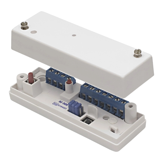
GENERAL
IU 300 is a relay and analyzer unit to be used with glass break
detectors in the GD 335 series of intruder alarm systems and up
to 20 detectors can be connected to one IU 300 unit. When an
alarm occurs the IU 300 relay and analyzer unit will activate a
free relay opening which should be connected to the control
panel input chosen at installation
FUNCTION
IU 300 measures resistance changes in a balanced alarm loop
with the end of line resistance of 2,2K ohms. At a change of +/-
40% and a duration of at least 200ms an alarm will be raised on
the normally closed alarm relay which will open for
approximately 2-3 seconds or will remain open until a manual
reset is completed. This depends upon the programming of the
unit. Reset is completed either locally on the reset button or
from a control panel by switching off the supply to the unit.
IU 300 has a tamper switch protection should an attempt be
made to open the lid.
PROGRAMMING
The IU 300 has 4 programming jumpers, (see fig), with which the
unit's basic settings are programmed
S1
Closed
The alarm relay stays open until manual
reset is completed.
Open The alarm relay opens for 2-3 seconds and is
automatically reset. The LED shows that it has been
an alarm and the LED is manually reset.
S2
Closed Power supply is 9 - 15V DC.
Open Power supply is 18 - 30V DC.
S3
Closed Reset with negative trigger.
Open Must be open if S4 is closed.
S4
Closed Reset with positive trigger.
Open Must be open if S3 is closed.
© 2016 Alarmtech – www.alarmtech.se
IMPORTANT!
Never mount the programming jumpers S3 and S4 at the
same time. The IU 300 is supplied with jumper S1-S3 inserted.
MOUNTING
1.
Select a suitable mounting point on an even surface.
Mount the unit with the screws provided.
2.
Connect the glass break detectors to the terminals 3 and 4.
Connect the end of line resistor of 2.2K Ω, 1 %.
3.
Connect as shown in the figure below.
4.
Program the unit with jumper S1-S4.
5.
Connect the power supply.
6.
Test alarm in each detector individually to ensure that they
all work correctly.
CONNECTING THE DETECTORS
The detectors in the GD 335-series are not polarity dependent.
All conductors in the cable are tinned. One of the two pairs is
taped together. If the tap e is·missing or the cable has been cut
there will be no contact within the pairs and no connection
between them. Connect the detectors as shown below.
TECHNICAL DATA
Power supply:
Max ripple:
Current consumption:
Current consumption alarm:
Alarm output:
Alarm loop:
- Threshold:
- Response time:
- Reset time:
Temperature range:
HF- immunity
Dimensions
Weight:
Colour:
Approvals:
Analyzer for GD 335
IU 300
9-15V DC l 18-30V DC
+/- 1Vpp at 12V
10mA
14-36mA
Relay contact, 33 ohm in
series. 1OOmA / 35V
2,2k ohm, 1% EOL-resistance
+/-- 40%
200ms
10ms
-10 to +50° C
>10V/m, 0,1 -1000MHz
92 x 31 x24 mm
0,04 kg
White or brown plastic housing
or grey metallic housing
VdS Klasse C, G194021 ,
SBSC Alarm Class 4.
IU 300 Manual 1643en
Advertisement
Table of Contents

Related Manuals for Alarmtech IU 300


Summary of Contents for Alarmtech IU 300
- Page 1 Program the unit with jumper S1-S4. Connect the power supply. IU 300 is a relay and analyzer unit to be used with glass break Test alarm in each detector individually to ensure that they detectors in the GD 335 series of intruder alarm systems and up all work correctly.
- Page 2 © 2016 Alarmtech – www.alarmtech.se IU 300 Manual 1643en...
- Page 3 © 2016 Alarmtech – www.alarmtech.se IU 300 Manual 1643en...
Need help?
Do you have a question about the IU 300 and is the answer not in the manual?
Questions and answers