Table of Contents
Advertisement
Quick Links
Advertisement
Table of Contents

Related Manuals for Midcontinent MD302-3


Summary of Contents for Midcontinent MD302-3
- Page 1 Manual Number 9018233 Revision C February 21, 2022...
- Page 2 FOREWORD This manual provides information intended for use by persons who, in accordance with current regulatory requirements, are qualified to install this equipment. If further information is required, please contact: Mid-Continent Instruments and Avionics Attn: Customer Service Dept. 9400 E. 34th Street N. Wichita, KS 67226 USA PH (316) 630-0101 FX (316) 630-0723...
-
Page 3: Table Of Contents
TABLE OF CONTENTS SECTION 1 GENERAL DESCRIPTION 4 1.1 INTRODUCTION 4 1.2 TECHNICAL SPECIFICATIONS 5 1.3 ARINC DATA LABELS 6 1.4 IMPORTANT SAFETY INFORMATION 7 SECTION 2 PRE-INSTALLATION CONSIDERATIONS 8 2.1 EQUIPMENT LOCATION 8 2.2 LIMITATIONS 9 2.3 MODIFICATION 10 SECTION 3 ... - Page 4 REVISION HISTORY Date Detail Approved 12/22/2014 Production release. 05/11/2018 Added TSO C6e and support information for use of MD32 Magnetometer. ARINC pass-through feature. Updated pinout. Add patent reference. 02/21/2022 Updated style and brand to meet Marketing and Engineering guidelines. Updated Section 3.2 and 3.4 with o-ring replacement information.
-
Page 5: Section 1 General Description
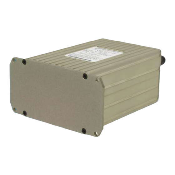
SECTION 1 GENERAL DESCRIPTION INTRODUCTION The model MD302 series SAM® Standby Attitude Module is a self-contained situational awareness instrument that provides aircraft attitude, altitude, airspeed, and slip indication, plus available heading data with the optionally installed MD32 Magnetometer. The remote version of the MD302, part number 6420302-3, is specifically designed as a compact and innovative solution for maximum flexibility, providing the needed positional awareness for navigation, autopilot function, or related applications. -
Page 6: Technical Specifications
TECHNICAL SPECIFICATIONS Electrical Attributes Input Voltage: 10-32 VDC Input Power: 4 watts (0.12A @ 28VDC) Output Power: Reserved for MD32 Remote Magnetometer (pin 11) Lighting Input: Input Data: ARINC 429 (see Table 1.1) Output Data: ARINC 429 (see Table 1.1); discrete valid signal to ground;... -
Page 7: Arinc Data Labels
ARINC DATA LABELS All labels are defined as Equipment ID 038 in BNR format. High and Low speed options for ARINC outputs are configurable. ARINC 429 Input Speed Label Description High magnetic heading altitude (rel 29.92) baro altitude baro correction (mbar) baro correction (inHg) magnetic heading ARINC 429 Output... -
Page 8: Important Safety Information
IMPORTANT SAFETY INFORMATION Read this safety information BEFORE maintaining or servicing the unit. Symbol Definition This section describes the precautions necessary for safe operations. The following safety symbols have been placed throughout the guide. WARNING Warnings identify conditions or practices that could result in personal injury. CAUTION Cautions identify conditions or practices that could result in damage to the equipment. -
Page 9: Section 2 Pre-Installation Considerations
SECTION 2 PRE-INSTALLATION CONSIDERATIONS EQUIPMENT LOCATION The MD302 SAM (-3) Standby Attitude Module is designed to be installed in the instrument panel or equipment bay of the aircraft. However, within the limitations of the environmental qualifications, other locations may be acceptable when considered within the context of the specific application and with the appropriate installation certification. -
Page 10: Limitations
LIMITATIONS The conditions and tests for TSO approval of this article are minimum performance standards. Those installing this article on or in a specific type or class of aircraft must determine that the aircraft installation conditions are within the TSO standards, specification of the article, and deviations listed below. -
Page 11: Modification
MODIFICATION This product has a nameplate that identifies the manufacturer, part number, description, certification(s) and technical specifications of the unit. It also includes the “MOD” or modification number representing notable changes in the hardware design of the unit. Modification (MOD) 0 is the initial release of the product and is identified on the nameplate by the lack of marking on the MOD numbers 1 through 9 (i.e. -
Page 12: Section 3 Installation
SECTION 3 INSTALLATION GENERAL INFORMATION This section contains interconnect diagrams, mounting dimensions and other information pertaining to the installation of the MD302 SAM Standby Attitude Module. After installation of cabling and before installation of the equipment, ensure that power is applied only to the pins specified in the interconnect diagram. - Page 13 Wire Gauge Selection Wire gauge should be 22 AWG. Use of PTFE, ETFE, TFE, Teflon, or Tefzel insulated wire is recommended for aircraft use per MIL-DTL-16878 or equivalent. Additionally, for data signals associated with ARINC 429 inputs and outputs, shielded twisted pair wiring per M27500 or equivalent is recommended (pin pairs 3 &...
- Page 14 To assemble the aircraft cable harness and Configuration Module refer to the following instructions and Figure 3.2: Install a pin/socket as supplied in the Connector Kit using an appropriate crimping tool for each wire in the aircraft cable harness. Be sure to make the harness long enough to remove the unit from the front of the panel without stressing the harness (approx.
-
Page 15: Pitot / Static Connections
Loosely connect the two halves of the Cable Strain Relief Clamp with (2) screws (Item 8). 10) Place the Cable Strain Relief Clamp in the Backshell as shown. 11) Bend the wires of the Configuration Module PC Board Assembly 180 degrees so that the PC Board has its electrical components facing down as shown. - Page 16 Item Qty Part Number Description 9017218 Backshell, Size 9 9017274 Cover, Backshell 9017184-1 PCB Assy, Config Module 9016479 Kit, DSub, 15pin HD part of 9016479 DSub Backshell Spring Clip part of 9016479 DSub Slide Lock, Size 9 part of 9016479 DSub Backshell Cable Clamp 90-406-00011 Screw 4-40X3/16 Pan Phil Blk Patch 90-208-10011...
-
Page 17: Installation Completion
INSTALLATION COMPLETION Prior to operating the unit in the aircraft, verify the basic operation of the unit and conduct a standard leak check of the pitot/static system per the aircraft maintenance manual or industry practice. Configuration information is stored on the configuration module, allowing easy replacement of the MD302. - Page 18 FIGURE 3.3 MD302 OUTLINE DRAWING Unit Versions Part Number Bezel Battery 6420302-1 Black 6420302-2 Black 6420302-3 None* 6420302-4 Gray 6420302-5 Gray 6420302-6* Black * remote mounted unit version. Contact manufacturer for details. TABLE 3.2 MD302 UNIT VERSIONS Manual Number 9018233 Revision C, February 21, 2022...
-
Page 19: Section 4 Operation
SECTION 4 OPERATION IMPORTANT: THE UNIT IS NOT APPROVED FOR FLIGHT UNTIL IT HAS BEEN CONFIGURED FULLY USING THE INSTRUCTIONS IN THIS SECTION! This section contains information on how to configure the aircraft specific requirements available with the MD302 SAM Standby Attitude Module. This includes critical flight parameters that contribute to the safe and certified operation of the unit and the aircraft. -
Page 20: Calibration
Panel Roll is specified in units of degrees from { 5.0 } to { -5.0 }. This compensates for minor roll error in the installation. Fractions of a degree may be entered, but will be rounded to 0.5° increments. The defaults are shown in the above example. If any parameters are omitted from the file, the configuration unit will retain its current setting. - Page 21 Procedure 1. Power off MD302. 2. Uncover the USB port and insert flash drive containing the configuration file. 3. Power on MD302. 4. The STATUS indicator will blink green while calibration is processed. 5. The RESULT indicator will illuminate green if the calibration is successful. 6.
- Page 22 Figure 4.1 MAGNETOMETER INSTALLATION ORIENTATIONS Manual Number 9018233 Revision C, February 21, 2022...
- Page 23 Procedure 1. Prepare the flash drive. a. On an empty, FAT32 formatted flash drive create a file named “mc_magc.dat”. b. Use a text editor to place the following two lines in the file: INCLINATION_ANGLE=45.000 MAG_ORIENTATION=0 c. Replace the inclination angle in the file with the correct inclination angle (in degrees) for your calibration location with up to 3 decimal places.
-
Page 24: Section 5 Conformance
SECTION 5 CONFORMANCE INSTRUCTIONS FOR CONTINUED AIRWORTHINESS Pressure System and Altimeter Verification Per federal regulation 14 CFR 91.411, it is required that each static pressure system and each altimeter have been tested and inspected within the last twenty-four (24) months. Software Updates Mid-Continent will have, on occasion, the need to update the software of the MD302 to maintain, improve and/or enhance functionality or performance. - Page 25 LOAD SOFTWARE 1. Insert flash drive containing the configuration file. 2. Power on MD302. 3. The STATUS indicator will blink green while the update is processed. 4. The RESULT indicator will illuminate green if the update was successful. 5. Remove the USB stick while power remains on. 6.
-
Page 26: Environmental Qualification Statement
ENVIRONMENTAL QUALIFICATION STATEMENT MODEL NUMBER: MD302 Series PART NUMBER: 6420302-( ) DESCRIPTION: 2-inch Standby Attitude Module (SAM) CERTIFICATION: FAA TSO-C2d (Type B), C3e, C4c, C6e, C10b, C106, C113a, C179a MANUFACTURER: Mid-Continent Instrument Co., Inc. ADDRESS: 9400 E. 34 St. North, Wichita, KS 67226, USA. SPECIFICATION: Test Specification (TS) 302 Test Data Sheet (TDS) 302 STANDARD:...
Need help?
Do you have a question about the MD302-3 and is the answer not in the manual?
Questions and answers