Table of Contents
Advertisement
Advertisement
Table of Contents

Related Manuals for Midcontinent MD302 Series


Summary of Contents for Midcontinent MD302 Series
- Page 1 INSTALLATION MANUAL AND OPERATING INSTRUCTIONS MODEL MD302-( ) SERIES STANDBY ATTITUDE MODULE Mid-Continent Instrument Co., Inc. dba Mid-Continent Instruments and Avionics 9400 E. 34 Street N. Wichita, KS USA 67226 (800) 821-1212 Manual Number 9017782 (316) 630-0723 Rev B, October 31, 2012...
- Page 2 Mid-Continent Instruments and Avionics, Wichita, KS FOREWORD This manual provides information intended for use by persons who, in accordance with current regulatory requirements, are qualified to install this equipment. If further information is required, please contact: Mid-Continent Instruments and Avionics Attn: Customer Service Dept.
- Page 3 Mid-Continent Instruments and Avionics, Wichita, KS REVISION HISTORY Date Approved Detail 09/10/12 Engineering release. 10/02/12 Initial release. 10/31/12 Updates implemented. REV. B, October 31, 2012 Manual Number 9017782...
-
Page 4: Table Of Contents
Mid-Continent Instruments and Avionics, Wichita, KS Table of Contents SECTION 1 GENERAL DESCRIPTION INTRODUCTION SYSTEM OVERVIEW 1.2.1 PRE-FLIGHT MODE ....................7 1.2.2 FLIGHT MODE ......................7 1.2.3 EMERGENCY MODE ....................9 ... - Page 5 Mid-Continent Instruments and Avionics, Wichita, KS SECTION 4 CONFIGURATION SETUP CONFIGURATION MODE/MENU CONFIGURE DISPLAY 4.2.1 ROLL DISPLAY ....................... 35 4.2.2 AIRSPEED UNITS ....................35 4.2.1 DISPLAY ORIENTATION ..................36 ...
-
Page 6: General Description
GENERAL DESCRIPTION INTRODUCTION The model MD302 series Standby Attitude Module is a self-contained situational awareness instrument that provides aircraft attitude, altitude, airspeed and slip indication. The compact and innovative design of the MD302 is specifically developed for maximum flexibility for installation in retrofit or modern instrument panel. -
Page 7: System Overview
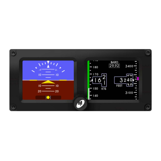
Mid-Continent Instruments and Avionics, Wichita, KS SYSTEM OVERVIEW The MD302 has four specific modes of operation. They are: Pre-flight Mode Flight Mode Emergency Mode Configuration Mode The following sections will briefly introduce each mode with further details provide within Sections 3 and 4 of this manual. - Page 8 Mid-Continent Instruments and Avionics, Wichita, KS In Flight Mode, the unit operates normally by displaying attitude, altitude, airspeed and slip information as shown in Figure 1.2. roll/bank scale pitch scale symbolic airplane slip indicator Figure 1.2 barometer value altitude window altitude trend bar airspeed window altitude units...
-
Page 9: Emergency Mode
Mid-Continent Instruments and Avionics, Wichita, KS 1.2.3 EMERGENCY MODE In Emergency Mode, aircraft power to the instrument has been lost and the unit continues to operate in Flight Mode utilizing power from the internal battery. The battery icon is displayed as shown in Figure 1.3. battery icon FIGURE 1.3 1.2.4... -
Page 10: Electrical Attributes
Mid-Continent Instruments and Avionics, Wichita, KS TECHNICAL SPECIFICATIONS 1.3.1 ELECTRICAL ATTRIBUTES Characteristics: Input Voltage: 10-32 VDC Input Power: (nominal) 4 watts (0.15A @ 28VDC) (maximum) 25 watts max (when charging and heating battery) Lighting Input: 5.14, or 28VDC or automatic photocell control Input Data: barometer synchronization via ARINC 429 (see Table 1.5) Output Data:... - Page 11 Mid-Continent Instruments and Avionics, Wichita, KS ARINC DATA LABELS All labels are defined as Equipment ID 038 in BNR format. High and Low speed options are configurable. See Section 3.4. ARINC 429 Input Speed Label Description High altitude (rel 29.92) baro altitude ARINC 429 Output Speed...
-
Page 12: Installation
Mid-Continent Instruments and Avionics, Wichita, KS SECTION 2 INSTALLATION GENERAL INFORMATION IMPORTANT: READ THIS ENTIRE SECTION PRIOR TO STARTING INSTALLATION! This section contains interconnect diagrams, mounting dimensions and other information pertaining to the installation of the MD302Digital Flight Instrument. After installation of cabling and before installation of the equipment, ensure that power is applied only to the pins specified in the interconnect diagram. - Page 13 Mid-Continent Instruments and Avionics, Wichita, KS FIGURE 2.1 INSTALLATION ORIENTATION OPTIONS REV. B, October 31, 2012 Manual Number 9017782...
-
Page 14: Limitations
Mid-Continent Instruments and Avionics, Wichita, KS LIMITATIONS The conditions and tests for TSO approval of this article are minimum performance standards. Those installing this article, on or in a specific type or class of aircraft, must determine that the aircraft installation conditions are within the TSO standards, specification of the article, and deviations as listed above. -
Page 15: Cable Harness
Mid-Continent Instruments and Avionics, Wichita, KS CABLE HARNESS Construct the cable harness with regards to the instructions below and using the Connector Pinout of Table2.1 and Figure 2.2 and Configuration Module Assembly of Figure 2.3. Installers should follow industry-accepted practices regarding aircraft wiring and applicable regulatory and advisory requirements and guidance. - Page 16 Mid-Continent Instruments and Avionics, Wichita, KS To assembly the aircraft cable harness and Configuration Module refer to the following instructions and Figure 2.3: Install a pin/socket as supplied in the Connector Kit using an appropriate crimping tool for each wire in the aircraft cable harness. Be sure to make the harness long enough to remove the unit from the front of the panel without stressing the harness (approx.
- Page 17 Mid-Continent Instruments and Avionics, Wichita, KS Item Qty Part Number Description 9017218 Backshell, Size 9 9017274 Cover, Backshell 9017184-1 PCB Assy, Config Module 9016479 Kit, DSub, 15pin HD part of 9016479 DSub Backshell Spring Clip part of 9016479 DSub Slide Lock, Size 9 part of 9016479 DSub Backshell Cable Clamp 90-406-00011...
-
Page 18: Configuration Module
Mid-Continent Instruments and Avionics, Wichita, KS PITOT / STATIC CONNECTIONS The connector kit supplied with the unit contains two (2) pneumatic quick disconnect fittings. These fittings are specific to the connections on the rear of the unit and required for proper operation. Aircraft tubing that connects to the unit must be ¼”... - Page 19 Mid-Continent Instruments and Avionics, Wichita, KS 5.50 4.82 5.22 2.4" diagonal 2.37 2.09 active area 4X Ø0.150 thru 3.16 Battery access 2.30 static port 15-pin D-sub pitot port USB access FIGURE 2.4 MD302 OUTLINE DRAWING REV. B, October 31, 2012 Manual Number 9017782...
- Page 20 Mid-Continent Instruments and Avionics, Wichita, KS 4X Ø.16±0.01 thru w Ø 0.175 X 82° countersink 4X R 0.10 max only 1 of 3 required per side .295 .750 2.34±0.02 2.090 .750 3.25±0.05 .295 5.220 FIGURE 2.5 PANEL CUTOUT STEP 1 STEP 2 FIGURE 2.6 INSTALL ILLUSTRATION...
-
Page 21: Operation
Mid-Continent Instruments and Avionics, Wichita, KS SECTION 3 OPERATION IMPORTANT: READ THIS ENTIRE SECTION PRIOR TO OPERATING THE UNIT IN FLIGHT! This section contains information on how to use and interpret the information presented to the pilot and crew during normal and emergency operation of the MD302 Digital Flight Instrument. USER INTERFACE The MD302 Digital Flight Instrument is designed for simple, intuitive operation for ease of use and quick interpretation of the information displayed. -
Page 22: Flight Mode
Mid-Continent Instruments and Avionics, Wichita, KS FIGURE3.1 FIGURE 3.1 (cont) PRE-FLIGHT MODE FLIGHT MODE In Flight Mode, the unit operates normally by displaying the four major functions of attitude, altitude, airspeed and slip information as shown in Figure 3.2. The Options Menu and brightness adjustment are also accessible in Flight Mode. -
Page 23: Major Functions
Mid-Continent Instruments and Avionics, Wichita, KS 3.3.1 MAJOR FUNCTIONS While in Flight Mode, the MD302 provides four major functions: attitude, altitude, airspeed and slip indication. 3.3.1.1 ATTITUDE OPERATION roll/bank scale pitch scale symbolic airplane horizon line slip indicator FIGURE 3.3 The attitude indicator portion of the display will always appear on the left display when the unit is oriented horizontally and on the top display when oriented vertically. -
Page 24: Altitude Operation
Mid-Continent Instruments and Avionics, Wichita, KS FIGURE 3.4 3.3.1.2 ALTITUDE OPERATION altitude tape/scale barometer value altitude window altitude trend bar altitude units FIGURE 3.5 The altimeter or altitude portion of the display will always appear on the right side of the right display when mounted horizontally and on the right side of the bottom display when mounted vertically. -
Page 25: Airspeed Operation
Mid-Continent Instruments and Avionics, Wichita, KS the altitude tape of the current altitude. Altitude units appear below the altitude window and can be changed during Flight Mode using the Options Menu (see Section 3.3.2). The altitude tape is a vertical scale along the right margin of the display. The current altitude is always in the middle of the tape and indicated by the triangular pointer on the right side of the altitude window. -
Page 26: Slip Operation
Mid-Continent Instruments and Avionics, Wichita, KS The airspeed indicator portion of the display will always appear on the left side of the right display when mounted horizontally and on the left side of the bottom display when mounted vertically. An example of the airspeed display is shown in Figure 3.6. The airspeed indicator display consists of three parts: the airspeed window, the airspeed tape, and the airspeed limitations or range markings. -
Page 27: Option Settings
Mid-Continent Instruments and Avionics, Wichita, KS 3.3.2 OPTION SETTINGS While in Flight Mode, aOption Settings menu is available to the pilot or cockpit crew members. The Option Settings offer multiple options that do not affect the aircraft specific configuration of the unit (these must be set in Configuration Mode by authorized personnel during installation and/or maintenance). -
Page 28: Alt Units
Mid-Continent Instruments and Avionics, Wichita, KS 3.3.2.2 ALT UNITS The ALT UNITS setting allows the user to select the altimeter or altitude units to either FEET or METERS. This feature is provided during flight in the event that the aircraft crosses airspace boundaries that require or report different altitude units. -
Page 29: Att Mask
Mid-Continent Instruments and Avionics, Wichita, KS FIGURE 3.11 3.3.2.5 ATT MASK The ATT MASK setting allows the user to turn the attitude mask ON or OFF. The attitude mask provides gradient dimming of the corners of the attitude display to give the aesthetic look of a round instrument. -
Page 30: Power Off
Mid-Continent Instruments and Avionics, Wichita, KS FIGURE 3.14 3.3.2.7 POWER OFF The POWER OFF action allows the user to immediately turn the unit off when it is operating on its internal battery and there is no significant motion or airspeed detected. -
Page 31: Exit Menu
Mid-Continent Instruments and Avionics, Wichita, KS 3.3.2.9 EXIT MENU The EXIT MENU action allows the user to manually exit the Options Menu and return to the active attitude indicator display. There are no selectable options. After confirming any setting by selecting it, that setting will become active and be saved in memory, regardless of whether the EXIT MENU command is selected or it times out (approximately 10 seconds of inactivity) and automatically reverts to the attitude display. -
Page 32: On The Ground
Mid-Continent Instruments and Avionics, Wichita, KS battery icon FIGURE 3.18 EMERGENCY OPERATION When operating on battery power and it becomes low, the battery icon will change to the low battery icon. This is identified by a black battery icon with a red X on it. This indicates that there is less than 20% of battery capacity left and may represent as little as 10 minutes of backup power available. -
Page 33: Configuration Setup
Mid-Continent Instruments and Avionics, Wichita, KS SECTION 4 CONFIGURATION SETUP IMPORTANT: THE UNIT IS NOT APPROVED FOR FLIGHT UNTIL IT HAS BEEN CONFIGURED FULLY USING THE INSTRUCTIONS IN THIS SECTION! This section contains information on how to configure the various requirements and options the MD302 Digital Flight Instrument offers in regards to the specific aircraft that it is installed in, including critical flight parameters that contributes to the safe and certified operation of the unit and the aircraft. -
Page 34: Configure Display
Mid-Continent Instruments and Avionics, Wichita, KS The CONFIGURE MENU root directory contains the following sub-menus and actions: CONFIGURE DISPLAY CONFIG DIMMING CONFIGURE AIRCRAFT UPDATE SOFTWARE ARINC SPEED BATTERY INFO POWER OFF ACCEPT CHANGES ... -
Page 35: Roll Display
Mid-Continent Instruments and Avionics, Wichita, KS 4.2.1 ROLL DISPLAY The ROLL DISPLAY setting allows the installer to select either the FIXED POINTER or FIXED SCALE option. With the FIXED POINTER, the roll scale containing the radial grads and triangles on the attitude display rotate with the horizon and the lower triangle pointer always points to the top of the display and represents the aircraft’s position in relation to the scale. -
Page 36: Display Orientation
Mid-Continent Instruments and Avionics, Wichita, KS 4.2.1 DISPLAY ORIENTATION The DISPLAY ORIENTATION setting allows the installer to select the orientation that the unit will be installed in the panel. It can be installed HORIZONTAL, VERTICAL RIGHT, or VERTICAL LEFT. In the HORIZONTAL orientation, the unit must be installed with the control knob at the bottom of the unit. -
Page 37: Dimming Control
Mid-Continent Instruments and Avionics, Wichita, KS 4.3.1 DIMMING CONTROL The DIMMING CONTROL setting allows the installer to select the source of dimming control. It can be an external source, typically the aircraft’s adjustable lighting bus, or it can use the INTERNAL photocell built into the unit which senses the ambient light conditions and adjusts the display brightness/dimming automatically. - Page 38 Mid-Continent Instruments and Avionics, Wichita, KS When setting the dimming curve with the dimming control set to external input (EXT 5V/EXT 14V/ EXT 28V), the X-axis of the dimming graph will read VOLTAGE and will range from 0 to (5, 14 or 28). This represents the voltage input of the lighting bus and shows the current input with the vertical blue line.
-
Page 39: Panel Tilt
Mid-Continent Instruments and Avionics, Wichita, KS Within the CONFIGURE AIRCRAFT sub-menu are the following options: PANEL TILT RANGE MMO RANGE MARKINGS EXIT CONFIG AIRCRAFT FIGURE 4.11 4.4.1 PANEL TILT The PANEL TILT setting allows the installer to input the angle of the instrument panel so that the attitude indicator will show zero pitch when in level flight. -
Page 40: Range Markings
Mid-Continent Instruments and Avionics, Wichita, KS FIGURE 4.13 MMO ENTRY PAGE AND SAMPLE SCREEN 4.4.3 RANGE MARKINGS The RANGE MARKINGS setting allows the installer to input airspeed limits (or “V-speeds”) specific to the aircraft. Aircraft airspeed limits can typically be found in the Pilot’s Operating Handbook (POH). -
Page 41: Configuration Mode Actions
Mid-Continent Instruments and Avionics, Wichita, KS CONFIGURATION MODE ACTIONS Configuration Mode Actions contain options that do not represent further sub-menus, but have single settings or initiate actions which exit the Configuration Mode. Figure 4.15 below shows the initial page of the Configuration Menu and the additional options at the bottom of the Configuration Menu page when scrolling down using the control knob. -
Page 42: Accept Changes
Mid-Continent Instruments and Avionics, Wichita, KS FIGURE 4.16 4.5.3 ACCEPT CHANGES When selecting ACCEPT CHANGES, all settings and changes made while in Configuration Mode are saved into permanent memory and saved to the Configuration Module memory as well. SETTINGS WILL NOT BE SAVED UNLESS “ACCEPT CHANGES” IS SELECTED WHEN DONE. -
Page 43: Conformance
Mid-Continent Instruments and Avionics, Wichita, KS SECTION 5 CONFORMANCE INSTRUCTIONS FOR CONTINUED AIRWORTHINESS 5.1.1 PRESSURE SYSTEM AND ALTIMETER VERIFICATION Per federal regulation 14 CFR 91.411, it is required that each static pressure system and each altimeter have been tested and inspected within the last twenty-four (24) months. 5.1.2 SOFTWARE UPGRADES Mid-Continent will have, on occasion the need to update software versions on the MD302 for... - Page 44 Mid-Continent Instruments and Avionics, Wichita, KS FIGURE 5.2 The altimeter instrument has failed, possibly due to exceedance of the pressure sensor range. This may self-correct, but if the error persists, immediately have the unit serviced. FIGURE 5.3 The airspeed instrument has failed, possibly due to exceedance of the pressure sensor range.
- Page 45 Mid-Continent Instruments and Avionics, Wichita, KS FIGURE 5.7 The configuration module has failed or is not installed properly. Internal settings will be used. If the configuration module is installed, it should be serviced immediately. FIGURE 5.8 Internal failure. Service unit immediately. FIGURE 5.9 Internal failure.
- Page 46 Mid-Continent Instruments and Avionics, Wichita, KS FIGURE 5.12 External settings (configuration module) were found to be invalid. The internal settings will be copied to the configuration module memory. Service unit if this error persists. FIGURE 5.13 Internal (unit) and external (configuration module) settings were found to be different.
-
Page 47: Environmental Qualification Statement
Mid-Continent Instruments and Avionics, Wichita, KS ENVIRONMENTAL QUALIFICATION STATEMENT NOMENCLATURE: 2-inch Standby Attitude Module MODEL NUMBER: MD302 Series PART NUMBER: 6420302-( ) TSO NUMBERS: C2d (Type B), C3e, C4c, C10b, C106, C113a, C179a MANUFACTURERS SPECIFICATIONS: Minimum Performance Specifications:TS302 (XX/XX/XX), TDS302 (XX/XX/XX)
Need help?
Do you have a question about the MD302 Series and is the answer not in the manual?
Questions and answers