Table of Contents
Advertisement
Quick Links
Advertisement
Table of Contents

Related Manuals for Interlogix IFS MC252-1T-1CXP


Summary of Contents for Interlogix IFS MC252-1T-1CXP
-
Page 1: Ifs Mc252-1T-1Cxp And Mc252-1P-1Cx User Manual
IFS MC252-1T-1CXP and MC252-1P-1CX User Manual P/N 1072682 • REV B • ISS 13NOV14... - Page 2 2014 United Technologies Corporation Copyright © Interlogix is part of UTC Building & Industrial Systems, a unit of United Technologies Corporation. All rights reserved. Trademarks and patents The IFS MC252-1T-1CXP and MC252-1P-1CX name and logo are trademarks of United Technologies.
-
Page 3: Table Of Contents
TABLE OF CONTENTS IFS MC252-1T-1CXP AND MC252-1P-1CX USER MANUAL ..........1 1. INTRODUCTION ........................4 1.1 P ...........................4 ACKAGE ONTENTS 1.2 P ...........................5 RODUCT EATURES 1.3 P ........................6 RODUCT PECIFICATIONS 2. INSTALLATION ........................10 2.1 P ........................10 RODUCT ESCRIPTION 2.1.1 Power over Coaxial Extender Front Panel...................11 2.1.2 LED Indicators ..........................11... -
Page 4: Introduction
1. INTRODUCTION Thank you for purchasing IFS Industrial Power over Coaxial Extender, MC252-1T-1CXP and MC252-1P-1CX. The descriptions of the two models are as follows: PoE over Coaxial Extender - Transmitter MC252-1T-1CXP (1-Port 10/100TX 802.3at PoE PD + 1-Port BNC PoE ) PoE over Coaxial Extender - Receiver MC252-1P-1CX (1-Port 10/100TX 802.3at PoE PSE + 12/24V DC Splitter) -
Page 5: Product Features
1.2 Product Features Physical Port Ports Model Name Copper MC252-1T-1CXP 1 x 10/100Base-TX (PoE IN) Power/Data Transmitter MC252-1P-1CX 1 x 10/100Base-TX (PoE OUT) Power/Data Receiver Power over Ethernet Eliminates Power cabling with PoE over Coaxial Ethernet over coaxial up to 1km with RG59U/RG6 75 Ohm Low Loss cable ... -
Page 6: Product Specifications
1.3 Product Specifications Model MC252-1T-1CXP MC252-1P-1CX Hardware Specifications 10/100Base-TX RJ-45 10/100Base-TX RJ-45 Auto-negotiation/ Auto-negotiation/ Copper Auto-MDI/MDI-X Auto-MDI/MDI-X 802.3at/af PoE Input 802.3at/af PoE Output BNC, female BNC, female Coaxial Power over Coaxial Output Power over Coaxial Input DC Socket 52~56V DC Input (Optional) 2-Position DIP Switch 2-Position DIP Switch(Front) - Page 7 Power over Ethernet/Coaxial IEEE 802.3at Type 2 PoE Standard IEEE 802.3af RJ-45 44~57V DC 48~56V DC, 600mA max. PSE Interface (Depend on what is the DC/PoE End-Span, Pin 1/2(+), 3/6(-) Power Input) RJ-45, both Mid-Span and PD Interface End-Span Input Range: 44~57V DC Input Range: 44~57V DC 12V DC, 2A max.
- Page 8 1.4 Physical Dimensions MC252-1T-1CXP: dimensions (W x D x H): 94 x 70.3 x 39.2 mm...
- Page 9 MC252-1P-1CX: dimensions (W x D x H): 94 x 70.3 x 39.2 mm...
-
Page 10: Installation
2. INSTALLATION This section describes the functionalities of the Industrial Power over Coaxial Extender’s components and guides you to how to install it on the desktop. Basic knowledge of networking is expected. Please read this chapter completely before continuing. 2.1 Product Description Power over Coaxial Based on IEEE 802.3at high power over Ethernet and up to 30 watts of power output, IFS PoE over coaxial extender solution eliminates the need for additional remote site power while allowing a single PoE... -
Page 11: Power Over Coaxial Extender Front Panel
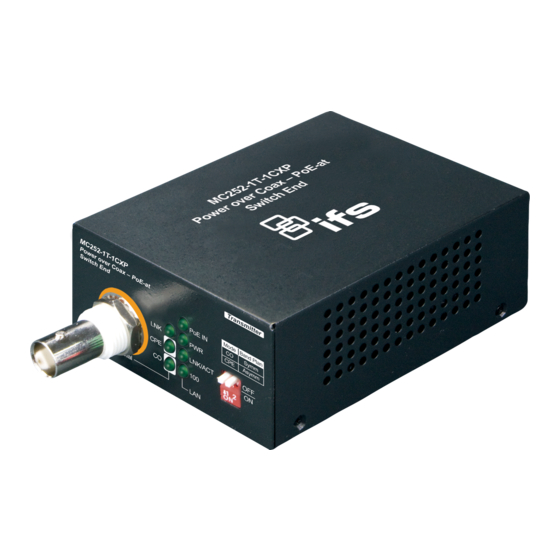
2.1.1 Power over Coaxial Extender Front Panel Figure 2-1 Figure 2-2 show the front panels of the MC252-1T-1CXP and MC252-1P-1CX Industrial Power over Coaxial Extenders. Figure 2-1: MC252-1T-1CXP front panel Figure 2-2: MC252-1P-1CX front panel Front Panel DIP Switch Setting The front panels of the MC252-1T-1CXP and MC252-1P-1CX provide one 2-DIP switch which is for configuring coaxial link CO/CPE mode and Band plan function. -
Page 12: Power Over Coaxial Extender Rear Panel
RJ-45 10/100Base-TX Interfaces Color Function Light: indicates the extender is successfully connecting to the network at 100Mbps. Green OFF: indicates the extender is successfully connecting to the network at 10Mbps. Blink: indicates the extender is actively sending or receiving data over LNK/ACT Green that port. -
Page 13: Applications Of Mc252-1T-1Cxp And Mc252-1P-1Cx
If there is no power socket in the network environment for Non-PoE networked device, the MC252-1P-1CX can be of great help by conveniently and easily providing this Ethernet device with DC power. Via the DIP switch configuration, the MC252-1P-1CX separates the power out and provides two kinds of DC power output and its voltage and current are shown below: ... - Page 14 Type 2 – MC252-1T-1CXP with 52~56V power adapter and MC252-1P-1CX with DC power output MC252-1T-1CXP MC252-1P-1CX Power adapter with 52~56V DC in BNC with DC power over Power Input coaxial input BNC with DC power over coaxial DC Terminal block with 12V or Power Output output 24V DC output...
- Page 15 The MC252-1T-1CXP accepts IEEE 802.3at equipment for optimal power injection. Any other Non-standard PoE Power devices may cause the MC252-1T-1CXP to malfunction. Type 4 – MC252-1T-1CXP with PoE power input and MC252-1P-1CX with DC power output MC252-1T-1CXP MC252-1P-1CX RJ-45 with 802.3at/af PoE input BNC with DC power over Power Input coaxial input...
-
Page 16: Troubleshooting
3. TROUBLESHOOTING This chapter contains information to help you solve issues. If the Industrial Power over Coaxial Extender is not functioning properly, make sure the Industrial Power over Coaxial Extender was set up according to instructions in this manual. VDSL LNK LED does not light after wire is connected to the VDSL port. CHECKPOINT: Verify the length of the wire connected between MC252-1T-1CXPand MC252-1P-1CX. -
Page 17: Appendix A: Networking Connection
APPENDIX A: NETWORKING CONNECTION A.1 Switch’s RJ-45 Pin Assignments 10/100Mbps, 10/100Base-TX RJ-45 Connector pin assignment MDI-X Contact Media Dependant Media Dependant Interface Interface -Cross Tx + (transmit) Rx + (receive) Tx - (transmit) Rx - (receive) Rx + (receive) Tx + (transmit) 4, 5 Not used Rx - (receive) - Page 18 SIDE 1 1 = White / Orange 1 = White / Green 2 = Orange 2 = Green 3 = White / Green 3 = White / Orange 4 = Blue 4 = Blue 5 = White / Blue 5 = White / Blue 6 = Green 6 = Orange 7 = White / Brown...
-
Page 19: Appendix B: Coaxial Cable Loss References
APPENDIX B: COAXIAL CABLE LOSS REFERENCES B.1 RG-6/U B.1.1 Physical Characteristics (Overall) B.1.1.1 Conductor Gauge: #Coax Stranding Conductor Material Dia. (in.) Solid BC-Bare Copper .040 B.1.1.2 Insulation Material: Insulation Material Dia. (in.) GA-injected FPE-Foam Polyethylene .180 B.1.1.3 Outer Shield Material: Type Outer Shield Material Coverage (%) -
Page 20: Physical Characteristics (Overall)
Freq. (MHz) Attenuation (dB/100ft.) 1000 B.2 RG-59/U B.2.1 Physical Characteristics (Overall) B.2.1.1 Conductor Gauge: #Coax Stranding Conductor Material Dia. (mm) Solid BC-Bare Copper .8128 B.2.1.2 Insulation Material: Insulation Material Dia. (mm) GA-injected FPE-Foam Polyethylene 3.683 B.2.1.3 Outer Shield Material: Type Outer Shield Material Coverage (%) Braid... -
Page 21: Electrical Characteristics (Overall)
B.2.2 Electrical Characteristics (Overall) Nominal Characteristic Impedance: 75 ohm Nom. Inductance: 0 .318257 µH/ft. Nom. Capacitance Conductor to Shield: 53.4803 µF/ft. Nominal velocity of Propagation: 83%. Nominal Delay: 4.036 ns/ft. Nominal Conductor DC Resistance (DCR) at 20°C: 32.81 Ω/km. Nominal Outer Shield Conductor DC resistance (DCR) @ 20°C: 10.827 Ω/km Nominal Attenuation: Freq.
Need help?
Do you have a question about the IFS MC252-1T-1CXP and is the answer not in the manual?
Questions and answers